

SiCf/SiC的蠕变性能与其纤维和基体等组元密切相关。三代SiC纤维具有良好的结晶度和化学计量比, 其复合材料的抗蠕变性能显著优于一代和二代SiCf/SiC复合材料[8], 如Hi-NicalonTM SiCf/SiC的1300 ℃/120 MPa蠕变断裂时间仅为0.83 h[11]。而采用三代SylramicTM-iBN纤维后, SiCf/SiC的抗蠕变性能显著提高, 1315 ℃/120 MPa蠕变断裂时间超过180 h[9]。对于不同基体的SiCf/SiC来说, 化学气相渗透(CVI)SiC基体具有优异的抗蠕变性能, 但CVI SiCf/SiC的孔隙率较高, 其抗蠕变性能比熔体渗透(MI)制备的SiCf/SiC(MI SiCf/SiC)差。而MI SiCf/SiC基体中的游离硅又限制了其最高使用温度。前驱体渗透裂解(PIP)制备的SiCf/SiC(PIP SiCf/SiC)消除了游离硅, 但是由于PIP SiC基体中存在严重微裂纹, PIP SiCf/SiC的抗蠕变性能远比CVI SiCf/SiC和MI SiCf/SiC差。SiCf/SiC的抗蠕变性能还与温度和应力等外部因素有关, 如CVI Hi-NicalonTM SiC/SiC的蠕变机制随应力和温度的不同而变化, 当蠕变应力远低于比例极限应力(σPLS)时, 其1315 ℃/69 MPa的蠕变断裂时间大于300 h[12⇓-14], 蠕变行为由CVI SiC基体控制; 当应力大于σPLS时, 材料在蠕变过程中发生基体开裂等损伤, 氧化性气氛进入材料内部造成氧化损伤, 材料的蠕变断裂时间显著缩短[12], 蠕变行为主要由纤维控制。
目前我国已经突破了碳化硅纤维和SiCf/SiC制备的关键技术。为了推进SiCf/SiC在我国航空发动机的应用, 本工作研究了国产二代Cansas-II SiC纤维平纹编织布增强的SiCf/SiC(2D-SiCf/SiC)在空气中的拉伸蠕变行为, 蠕变温度为1200~1400 ℃, 蠕变应力为80~140 MPa, 获得了应力和温度对蠕变性能的影响规律, 并利用扫描电子显微镜(SEM)观察蠕变断口形貌, 进一步揭示了2D-SiCf/SiC的蠕变损伤机理。
1 实验方法
1.1 实验材料
表1 国产二代Cansas-II碳化硅纤维的基本性能
Table 1
| Diameter/ μm | Density/ (g·cm-3) | Tensile strength/GPa | Tensile modulus/GPa |
|---|---|---|---|
| 14 | 2.74 | 2.7 | 270 |
表2 2D-SiCf/SiC的拉伸性能
Table 2
| Temperature/℃ | E/GPa | σPLS/MPa | σUTS/MPa | ε/% |
|---|---|---|---|---|
| RT | 273 | 115 | 282 | 0.57 |
| 1200 | 259 | 110 | 249 | 0.74 |
| 1300 | 223 | 92 | 229 | 0.60 |
σUTS: Ultimate Tensile Strength
1.2 实验方法
使用电子万能试验机(DDL 100, 中机试验装备股份有限公司)测试2D-SiCf/SiC的室温拉伸性能, 试样形状和尺寸如图1所示。使用应变片(BE120- 10AA, 中航电测仪器股份有限公司)测量应变, 加载速率为0.5 mm/min, 得到2D-SiCf/SiC的拉伸应力-应变曲线, 从而计算出弹性模量(E)、强度极限(σUTS)、σPLS和断裂应变(ε)等性能。蠕变试验在电子蠕变试验机(RDL50, 中机试验装备股份有限公司)上进行。高温拉伸蠕变试样如图1所示。蠕变试验在大气环境中进行, 蠕变温度为1200、1300和1400 ℃, 蠕变应力为80~140 MPa。对于未发生蠕变断裂试样, 开展室温拉伸试验, 测量其剩余拉伸性能。
图1
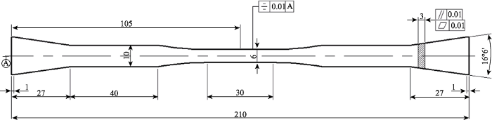
图1
拉伸和拉伸蠕变试样形状与尺寸(单位: mm)
Fig. 1
Dimensions and shape of tensile and tensile creep specimen (unit: mm)
利用SEM(TESCAN MIRA3, 捷克)观察试样的蠕变断裂断口形貌。切割试样近断口部分制成金相试样, 利用SEM观察纤维和基体损伤。利用SEM附带的电子能谱仪(EDS, OXFORD X-MaxN, 英国)分析纤维和基体的成分。
2 实验结果
2.1 蠕变曲线
图2显示了2D-SiCf/SiC的1200、1300和1400 ℃的典型蠕变曲线, 由图可见2D-SiCf/SiC 的蠕变曲线可分为减速蠕变和稳态蠕变两个阶段。随应力增加或温度升高, 稳态蠕变阶段缩短甚至会消失。
图2
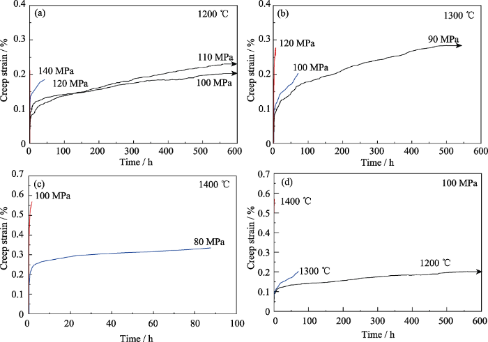
图2
2D-SiCf/SiC的高温拉伸蠕变曲线
Fig. 2
Tensile creep curves of 2D-SiCf/SiC at high temperatures
(a) 1200 ℃, different stress; (b) 1300 ℃, different stress; (c) 1400 ℃, different stress; (d) Different temperatures, 100 MPa
在相同温度下, 随应力增加, 蠕变断裂时间显著缩短, 如图2(a~c)所示: 当蠕变温度为1200 ℃, 蠕变应力为110 MPa时, 2D-SiCf/SiC的蠕变断裂时间超过560 h; 当应力增大至140 MPa时, 蠕变断裂时间不到1 h。同时, 在相同应力下, 随温度升高, 蠕变断裂时间缩短, 蠕变断裂应变增加。当蠕变应力为100 MPa时, 2D-SiCf/SiC的1200 ℃蠕变断裂时间超过560 h, 蠕变断裂应变小于0.2%; 当温度升高到1300 ℃时, 蠕变断裂时间缩短至70 h; 当温度达到1400 ℃时, 蠕变断裂时间不到2 h, 蠕变断裂应变增至0.57%, 如图2(d)所示。从图2还可以看出, 要延长2D-SiCf/SiC的蠕变断裂时间, 应在提高温度的同时, 降低蠕变应力。当蠕变温度由1200 ℃升高到1300 ℃, 蠕变应力由110 MPa降低到90 MPa时, 2D-SiCf/SiC的蠕变断裂时间超过500 h。进一步升高温度到1400 ℃, 即使蠕变应力降低至80 MPa, 蠕变断裂时间也仅为80 h。从图2还可看出, 在 1200和1300 ℃下, 蠕变断裂应变随应力升高, 表现出先减小后增大的趋势。文献研究表明: 在相同的蠕变时间内, 应力增加会提高蠕变速率, 2D- SiCf/SiC的蠕变断裂应变也随之升高; 当应力过高, 蠕变断裂时间大幅缩短, 导致应变降低[11⇓⇓-14]。因此, 蠕变断裂应变的减小与增大受应力和蠕变断裂时间的影响。蠕变断裂应变先减小是由于蠕变断裂时间大幅缩短(从大于500 h降至几十小时), 后增大是因为应力增加导致蠕变速率增大了1~2个数量级。
根据图2所示的蠕变曲线, 可得到稳态蠕变速率、蠕变断裂应变, 蠕变断裂时间等性能参数, 见表3。可以看出, 稳态蠕变速率随温度升高或应力增加而增大, 且蠕变断裂时间越长, 稳态蠕变速率越小。稳态蠕变速率在1×10⁻¹⁰~5×10⁻¹⁰ /s之间时, 蠕变断裂时间超过500 h; 稳态蠕变速率约为10-9 /s左右时, 蠕变断裂时间为10~100 h; 稳态蠕变速率大于10-8 /s时, 蠕变断裂时间不到10 h。表3同时列出了日本朱世杰[13]和美国GE[15]等获得的MI-SiCf/SiC和CVI-SiCf/SiC两种国外二代材料在相近条件下的蠕变性能。可见, 国产2D-SiCf/SiC的稳态蠕变速率与两种国外材料接近, 但是其蠕变断裂时间显著少于MI-SiCf/SiC。
表3 2D-SiCf/SiC复合材料在空气中的高温拉伸蠕变性能
Table 3
| Specimen | Tempera- ture/℃ | Stress/ MPa | Steady-state creep strain rate/s-1 | Creep rupture time/h | Creep strain/% |
|---|---|---|---|---|---|
| 2D-SiCf/SiC | 1200 | 100 | 1.86×10⁻¹⁰ | >560 | 0.20 |
| 1200 | 110 | 4.95×10⁻¹⁰ | >560 | 0.23 | |
| 1200 | 120 | 2.16×10⁻⁹ | 42 | 0.18 | |
| 1200 | 140 | 8.45×10⁻⁷ | 0.1 | 0.21 | |
| 1300 | 90 | 5.62×10⁻¹⁰ | >500 | 0.28 | |
| 1300 | 100 | 1.73×10⁻⁹ | 70 | 0.20 | |
| 1300 | 120 | 1.86×10⁻⁸ | 6 | 0.28 | |
| 1400 | 80 | 1.32×10⁻⁹ | 88 | 0.33 | |
| 1400 | 100 | 1.46×10⁻⁸ | 1.6 | 0.57 | |
| CVI-SiCf/SiC[13] | 1300 | 75 | 2.3×10⁻⁹ | 111.1 | — |
| 1300 | 90 | 6.2×10⁻⁸ | 33.4 | — | |
| 1300 | 120 | 3.6×10⁻⁷ | 0.83 | — | |
| 1300 | 150 | 3.0×10⁻⁶ | 0.14 | — | |
| MI-SiCf/SiC[15] | 1204 | 125 | 3.0×10⁻¹¹ | >1000 | 0.25 |
| 1204 | 140 | 2.3×10⁻¹⁰ | >1000 | 0.31 | |
| 1204 | 150 | — | 82.1 | 0.29 |
2.2 剩余拉伸性能
对于未发生蠕变断裂的2D-SiCf/SiC, 进一步测试其室温拉伸性能, 获得了图3所示的剩余拉伸应力-应变曲线, 其剩余拉伸性能见表4。可见, 不同条件蠕变后, 2D-SiCf/SiC的剩余拉伸性能显著低于原始材料。随着蠕变应力增加或温度提高, 2D-SiCf/SiC的剩余拉伸性能保持率降低。1200 ℃/100 MPa蠕变560 h后, 2D-SiCf/SiC的σUTS保持率为75%; 若蠕变应力增大到110 MPa, σUTS保持率降低至61%, σPLS、E和ε降低至原始材料的77%、77%和44%。当温度升高至1300 ℃, 蠕变应力降低至90 MPa时, 2D-SiCf/SiC的拉伸性能保持率约为50%, 显著低于2D-SiCf/SiC在1200 ℃蠕变后的拉伸性能保持率, 说明蠕变温度对该材料的蠕变损伤影响更大。
图3
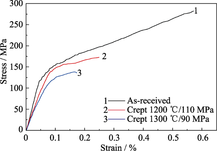
图3
不同状态的2D-SiCf/SiC的拉伸应力-应变曲线
Fig. 3
Tensile stress-strain curves of as-received and crept 2D-SiCf/SiC
表4 2D-SiCf/SiC蠕变后的剩余拉伸性能
Table 4
| σUTS/MPa | E/GPa | σPLS/MPa | ε/% | ||
|---|---|---|---|---|---|
| As-received | 282 | 273 | 115 | 0.57 | |
| Crept | 1200 ℃/100 MPa | 211 | — | — | — |
| 1200 ℃/110 MPa | 173 | 209 | 89 | 0.25 | |
| 1300 ℃/90 MPa | 138 | 157 | 55 | 0.17 | |
2.3 断口形貌
为进一步揭示2D-SiCf/SiC的蠕变机理, 观察了典型试样的断口形貌, 根据断口上的特征区域判断蠕变损伤。图4(a)为2D-SiCf/SiC的室温拉伸断口形貌, 整个断口表面均能看到纤维拔出。图4(b)为1200 ℃/110 MPa蠕变560 h后2D-SiCf/SiC的室温拉伸断口形貌, 断口大部分区域的特点与图4(a)相似, 能从断口上看到明显的纤维拔出, 说明对应的区域基本没有发生氧化, 为瞬断区; 在该试样断口的边缘和穿刺纤维附近, 断口平齐, 基本无纤维拔出现象, 为氧化区[16]。从两类区域面积大小可以判断,蠕变过程中材料内部没有发生明显氧化, 仅在试样边缘和穿刺纤维附近发生氧化。图4(c, d)是蠕变温度为1200 ℃, 蠕变应力分别为120和140 MPa下2D-SiCf/SiC蠕变断裂后的断口形貌。蠕变应力为120 MPa时, 蠕变断裂时间为42 h, 其断口的氧化区面积显著增大。瞬断区面积缩小, 该区域上的纤维拔出长度明显增加(图4(c))。蠕变应力为140 MPa时, 蠕变断裂时间仅为0.1 h, 这时断口上也能够看到氧化区和瞬断区, 其氧化区面积小于图4(c)。对比图4(b~d)可知, 不同蠕变时间导致的蠕变断口呈现不同的断口特点, 即蠕变时间越长, 氧化区面积越大。当蠕变应力较小时, 材料的基体开裂程度低, 到达材料内部的氧含量少, 即使蠕变时间大于560 h, 材料内部也没有发生明显氧化。蠕变应力增加, 基体开裂程度增大, 氧气能够通过基体裂纹或穿刺纤维等进入材料内部, 使得材料内部氧化程度增加。蠕变温度升高, 其断口宏观形貌也呈现类似特点。
图4
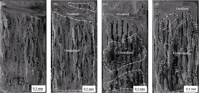
图4
2D-SiCf/SiC在不同条件下的断口宏观形貌
Fig. 4
Macroscopic morphologies of fractures of 2D-SiCf/SiC under different conditions
(a) As-received; (b) Crept at 1200 ℃/110 MPa for 560 h; (c) Crept at 1200 ℃/120 MPa; (d) Crept at 1200 ℃/140 MPa
前面结果可知2D-SiCf/SiC蠕变断裂断口氧化区的形成与蠕变过程密切相关, 蠕变过程中材料的氧化与蠕变温度、应力和时间等密切相关, 因此可从氧化区大小和形貌判断蠕变损伤过程。图5显示了2D-SiCf/SiC的3个典型蠕变断口的氧化区形貌, 其蠕变断裂时间分别是42、70和88 h。可以看出: 蠕变断口氧化区上没有纤维拔出现象, 纤维拔出长度短意味着纤维/基体界面结合强度高。2D-SiCf/SiC的不同温度断口氧化区形貌不同。1200 ℃/120 MPa蠕变断口氧化区表面形成氧化物(图5(a)), 据EDS分析可知, 这些氧化物主要为SiO2。蠕变温度升高至1300 ℃, 氧化程度加剧, SiO2熔体覆盖在材料断口氧化区表面, 同时可见图5(b)所示的气体溢出气泡。蠕变温度升高到1400 ℃时, 材料的氧化程度进一步加剧, 形成更多SiO2熔体覆盖于断口氧化区表面, 如图5(c)所示。因此蠕变温度越高或蠕变断裂时间越长, 蠕变断口表面的氧化程度越大。
图5
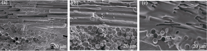
图5
2D-SiCf/SiC在不同条件蠕变断裂的断口氧化区形貌
Fig. 5
Morphologies of fracture oxidation zone of 2D-SiCf/SiC under different creep rupture conditions
(a) 1200 ℃/120 MPa; (b) 1300 ℃/100 MPa; (c) 1400 ℃/80 MPa
蠕变过程中, 界面处的BN氧化成B2O3气体逐渐挥发会造成纤维/基体界面间隙[17]。部分B2O3熔体可与基体或纤维氧化生成的SiO2融合形成了硼硅酸盐熔体。随着基体或纤维氧化程度增大, 硼硅酸盐熔体中SiO2含量增加, 其黏度增大, 最终固化为高SiO2含量的玻璃[18], 从而造成界面粘结, 如图6(a)所示。界面粘结将导致纤维/基体界面结合强度变大, 裂纹无法偏转, SiO2的填充也会增大应力集中程度, 进而使蠕变裂纹扩展, 造成蠕变断裂。此外, 在1200和1300 ℃蠕变断裂后, 还发现图6(b)所示的纤维氧化。这是因为在这两个温度下SiC的氧化速率低于1400 ℃的氧化速率。研究表明: 1300 ℃条件下, SiC氧化生成SiO2的速率为3.76×10⁻²μm2/h [19], 低于1400 ℃的氧化速率(5.89×10⁻²μm2/h)。没有生成足够的SiO2填充全部纤维/基体界面, 当BN界面被消耗形成空隙后, 纤维被氧化使其有效直径变小, 纤维强度降低, 进而造成纤维断裂。因此不论是界面粘结还是纤维氧化, 均会促使基体裂纹张开和扩展, 进而造成蠕变断裂。
图6
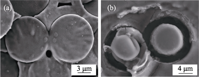
图6
1300 ℃/100 MPa 蠕变过程中2D-SiCf/SiC中发生的界面和纤维损伤
Fig. 6
Interface and fiber damage in 2D-SiCf/SiC during creeping at 1300 ℃/100 MPa
(a) SiO2 filled; (b) SiO2 unfilled
2.4 截面形貌
由前述结果可知, 2D-SiCf/SiC在1200 ℃/110 MPa和1300 ℃/90 MPa两种条件下均未发生蠕变断裂, 但是1300 ℃/90 MPa蠕变后, 复合材料的剩余拉伸性能显著下降。进一步分析两个试样的截面微观组织, 如图7所示, 1200 ℃/110 MPa蠕变560 h后, 纤维和界面保持相对完好, 复合材料内部没有看到明显的氧化; 1300 ℃/90 MPa蠕变500 h后, SiC纤维发生了开裂, 说明纤维在蠕变过程中发生了严重损伤, 其性能退化。这就是2D-SiCf/SiC 经1300 ℃/90 MPa蠕变500 h后的拉伸性能显著下降的原因。
图7
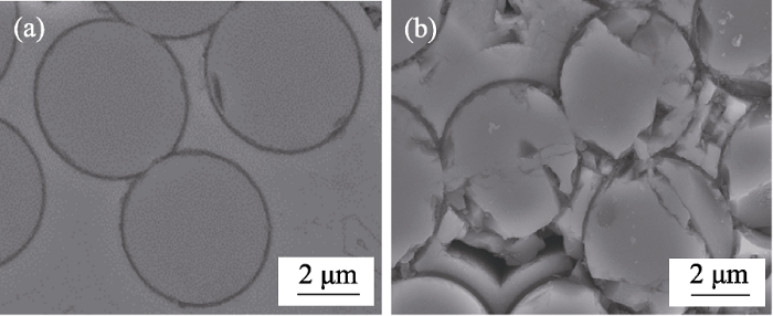
图7
2D-SiCf/SiC蠕变后的纵向纤维微观组织
Fig. 7
Longitudinal fiber microstructures of 2D-SiCf/SiC after crept
(a)1200 ℃/110 MPa for 560 h; (b)1300 ℃/90 MPa for 500 h
3 分析与讨论
实验结果显示2D-SiCf/SiC的蠕变行为和损伤模式与应力和温度密切相关, 当蠕变应力低于σPLS时, 2D-SiCf/SiC有良好的蠕变性能, 基体不会发生明显开裂, 氧气无法大量进入材料内部, 复合材料蠕变560 h后的拉伸断口也反映出这个特征。这时蠕变载荷由纤维和基体共同承担, 其蠕变行为由基体和纤维共同控制。当蠕变应力大于σPLS时, 基体发生明显开裂, 氧气通过基体裂纹进入材料内部, 使基体、纤维和界面发生氧化, 发生界面粘结和纤维氧化等损伤(如图6所示)。增加应力或提高温度, 基体开裂程度增大, 此时蠕变行为主要由纤维决定。更高的温度和应力造成纤维损伤程度加剧, 这与文献[9]的研究结果一致。
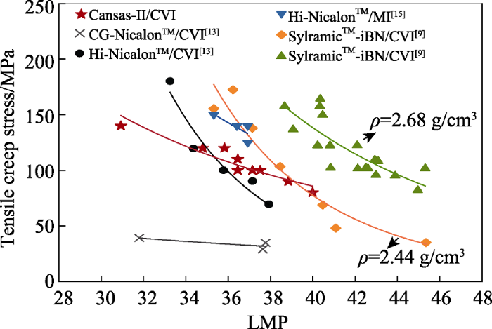
从表2可知, 随着温度升高, 2D-SiCf/SiC的σPLS下降。在相同应力下, 蠕变温度越高, σPLS下降越小, 2D-SiCf/SiC的基体开裂程度越大, 因此抗蠕变性能越差。2D-SiCf/SiC的σPLS与其使用的纤维和基体工艺密切相关[9]。本研究中2D-SiCf/SiC的σPLS与CVI Hi-Nicalon SiCf/SiC的接近[13], 但低于MI-SiCf/SiC的[15]。为进一步说明基体类型对于蠕变性能的影响, 这里使用Larson-Miller参数(LMP)估计和比较了不同基体类型SiCf/SiC的蠕变断裂时间[9]。LMP是将蠕变断裂时间与蠕变应力和温度建立联系的参数, 关系如公式(1)所示。对于SiCf/SiC, D为22[20]。图8显示了2D-SiCf/SiC在不同应力下的LMP参数, 为了对比还列出了部分不同基体和纤维的SiCf/SiC的数据[9,13,15]。从图中可以看出, 在相同条件下, 2D-SiCf/SiC的蠕变性能与其使用的纤维和基体类型密切相关。纤维代次越高, 2D-SiCf/SiC的抗蠕变性能越好。MI SiCf/SiC的抗蠕变性能优于CVI SiCf/SiC。
其中T是温度(K), tR是蠕变断裂时间, D是常数。
图8
4 结论
1) 在1200~1400 ℃温度范围内, 2D-SiCf/SiC的蠕变断裂时间随温度升高或应力增加而缩短。在1200 ℃/110 MPa条件下, 其蠕变断裂时间大于560 h, 最小蠕变速率为4.95×10⁻¹⁰ /s, 蠕变性能达到国外类似材料水平。
2) 2D-SiCf/SiC的蠕变断裂时间与氧化损伤程度密切相关。在1200 ℃/110 MPa条件下, 氧化区面积小, 蠕变断裂时间大于560 h。增加应力或提高温度会使氧化区面积增大, 蠕变断裂时间缩短。
3) 2D-SiCf/SiC在1200~1400 ℃的蠕变行为主要是基体开裂和氧化损伤。基体开裂后, BN界面氧化形成间隙, 被氧化的纤维直径明显减小, SiC氧化生成的SiO2填充界面导致界面粘结, 这进一步促使基体裂纹张开和扩展。
参考文献
Characterizing ceramic-matrix composites to improve durability
Research and development of continuous SiC fibers and SiCf/SiC composites

Polymer-derived method is the main preparation method for continuous SiC fiber. So far, three generations of SiC-based fibers have been developed. SiC fiber is mainly used as reinforcement for SiC matrix to prepare SiCf/SiC composite, which exhibits excellent properties such as high-temperature resistance, oxidation resistance, high-temperature creep resistance, and neutron radiation stability. Therefore, it is considered as a promising preferred alternative material for structural components which works under harsh environments. In this review, the domestic and oversea development of the polymer-derived SiC fibers are introduced, in particular the different approaches for preparation and the characteristics of the 3rd generation fibers. Then, the development of SiCf/SiC preparation technology and properties are reviewed and the relationship between the innovation in fabrication of SiCf/SiC composite and the development of SiC fiber is hightlighted. Finally, the application progress of SiCf/SiC composite in high performance aero-engines and fusion power cores is summerized. Meanwhile, some perspectives on the development of domestic SiC fibers and SiCf/SiC are also discussed.
Fracture behavior of SiC/SiC composites with different interfaces
SiC fiber reinforced SiC matrix composites (SiC/SiC) are promising materials for high temperature structural applications. In this work, SiC/SiC composites with Pyrolytic Carbon (PyC) interface or Carbon Nanotubes (CNTs) interface were fabricated by polymer infiltration and pyrolysis (PIP) process. Overall mechanical properties and interfacial shear strength of the SiC/SiC composites were characterized and crack growth processes were observed in situ by scanning electron microscope (SEM). The results indicate that flexural strengths of two types of SiC/SiC composites are similar, but the fracture toughness of the SiC/SiC composite with PyC interface is twice as much as that of the SiC/SiC composite with CNTs interface. Cracks propagate along the fibre-matrix interface in the SiC/SiC composite with PyC interface, which can be deflected or arrested by the PyC interface, hence the composite exhibits a pseudo-ductile fracture behavior. However, the CNTs interface fails to cease the crack in the SiC/SiC composite with CNTs interface, so the initial crack propagates rapidly through the fibers leading to final main crack, and a brittle fracture mode.
Tensile creep properties and damage mechanisms of 2D-SiCf/SiC composites reinforced with low-oxygen high-carbon type SiC fiber
Effect of fiber content on single tow SiC minicomposite mechanical and damage properties using acoustic emission
Matrix cracking in crossply ceramic matrix composites under quasi-static and cyclic loading
The stress dependence damage mechanism during tensile creep and fatigue in a SiC/SiC composite at 1400 ℃
Understanding of the behaviour and the influence of oxidation during creep of SiCf-SiBC composites in air.
Creep behavior and failure mechanisms of CVI and PIP SiC/SiC composites at temperatures to 1650 ℃ in air.
Creep properties and damage mechanisms of 2D-SiCf/SiC compositer prepared by CVI
The creep properties of 2D-SiCf/SiC composites prepared by chemical vapor infiltration were studied. The creep temperatures were 1200, 1300 and 1400 ℃, and the stress levels ranged from 100 MPa to 140 MPa. Scanning electron microscope was used to observe the fracture morphology, and their microstructure was analyzed by high resolution transmission electron microscope. The results show that the creep damage modes of 2D-SiCf/SiC composites mainly include the generation of matrix crack, interfacial debonding and fiber creep. The creep of bridging fibers leads to increase of the opening distance of the matrix cracks and further creep rupture of the composite. The microstructural stability of the SiC fiber plays a critical role in the creep properties of 2D-SiCf/SiC composites. SiC grains in the fibers of 2D-SiCf/SiC composites do not grow when it is crept at 1200 ℃/100 MPa. However, the grains grow significantly when the creep temperature increases to 1400 ℃. The creep rupture time decreases to 8.6 h from above 200 h, and the steady-state creep rate increases by three orders of magnitude.
Tensile creep and rupture of 2D-woven SiC/SiC composites for high temperature applications
Creep and fatigue behavior in Hi-NicalonTM-fiber-reinforced silicon carbide composites at high temperatures
Monotonic tension, fatigue and creep behavior of SiC-fiber-reinforced SiC-matrix composites: a review
Tensile creep behavior of a SiC-fiber/SiC composite at elevated temperatures
GE Global Research. Melt Infiltrated Ceramic Composites (Hipercomp®) For Gas Turbine Engine Applications
Intermediate temperature strength degradation in SiC/SiC composites
Microstructure and mechanical performance of SiCf/BN/SiC mini-composites oxidized at elevated temperature from ambient temperature to 1500 ℃ in air.
A comparison of the oxidation kinetics of SiC and SiN.
