

超高温氧化铝基复相陶瓷的高温综合力学性能优异, 在高温氧化性等极端恶劣环境下长期服役具有广阔的应用前景[1]。二十世纪六十年代以来, 烧结制备的Al2O3-TiCp(AT)复相陶瓷刀具广泛应用于硬质钢、高温合金或铸铁的高速切削[2]。研究者发现在Al2O3基体中弥散一定比例的TiCp可以进一步提高氧化铝陶瓷材料的硬度, 并且改善陶瓷材料的断裂韧性, 提高纯Al2O3陶瓷刀具的切削性能, 这是结构陶瓷有效的增韧方法[3-4]。采用传统热压法在35 MPa、近1700 ℃高温环境下制备的AT复合材料硬度可达18~22 GPa, 断裂韧性达3.75~4.00 MPa·m1/2[2⇓⇓-5]。GEVORKYAN等[6]采用热压法制备了断裂韧度为4.2 MPa·m1/2的TiC-Al2O3陶瓷刀具材料; 程寓等[7]采用微波烧结制备的Al2O3-TiCp显微硬度为19.6 GPa, 断裂韧性为4.8 MPa·m1/2。此外, 采用超过1800 ℃无压烧结+热等静压, 最终可以实现陶瓷致密化[8], 也能够达到与热压法制备样件同样的机械性能, 但是增加了加工成本, 延长了制备周期[9]。传统陶瓷成型方法, 如干压、凝胶注模、等静压、流延等对模具依赖性强, 而且烧结制备方法往往能耗高、周期长, 粉末烧结过程中还会产生孔洞和界面非晶相[10-11]。另外, 陶瓷的加工较为困难: 一方面切削刀具容易磨损, 另一方面加工过程中样件易产生变形、开裂等缺陷[12]。为了获得更高性能的AT材料, 必须探索短流程、低能耗的新型制备方法。
激光定向能量沉积技术(Laser Directed Energy Deposition, LDED)是一种高柔性的陶瓷基复合材料制备技术[13], 最初仅应用于制备低熔点金属材料, 随着成形工艺及装备的不断发展和优化, 应用范围逐渐扩展到高温难熔材料的一步近净成形[14]。该工艺利用高能量密度激光作为热源, 可以将同步输送的原材料粉末熔化, 通过逐层堆积成形[15]。与传统工艺相比, LDED可以在不烧结的情况下一步制备样品, 防止烧结过程中样品收缩变形以及引入黏结剂等杂质。此外, LDED在元件尺寸、结构和组成方面具有更灵活的适应性。利用“离散+堆积”的增材成形思想, 通过同步送粉实现工件的一步精确成形[16], 为了提高工件性能还可以在原料中掺杂增强颗粒来制备复合材料。增材制造技术具有设计自由度高、产品研发周期短、制造成本低等特点, 可无需模具快速地制造复杂结构陶瓷零件[17], 在定制高性能复杂样品方面具有广阔的应用前景。随着技术的发展, 研究人员已利用LDED技术成功实现了多种材料的直接增材制造, 如Al2O3/ZrO2功能梯度陶瓷、Al2O3/Al6Ti2O13、Al2O3/YAG、莫来石、磁性材料等, 并展现出极具前景的工艺特点与性能优势[18⇓⇓⇓⇓⇓-24]。然而, 目前利用LDED技术制备颗粒掺杂的陶瓷基复合材料的研究还鲜有报道, 尤其Al2O3-TiCp(AT)复相陶瓷的LDED工艺尚无得到系统研究, TiCp在Al2O3熔体中的存在形式及其对性能的影响规律尚不清晰, 相关内在机制也有待于进一步明确。
为此, 本研究开展了AT复相陶瓷材料的LDED成形实验, 通过改变TiCp掺杂比例, 系统研究了定参数下不同比例TiCp掺杂对AT复相陶瓷裂纹缺陷、相对密度、微观组织和力学性能的影响, 探讨并验证了利用LDED直接增材制造AT复相陶瓷的可 行性。
1 实验方法
1.1 实验设备及材料
实验在LDED系统中进行, 该系统由JK1002型Nd:YAG连续激光器(英国GSI Lumonics公司)、DPSF-2D双筒送粉系统(中航工业北京航空制造工程研究所)、数控机床、冷却系统和工业计算机等组成。波长1064 nm、平均功率为1000 W的激光作为能量源输入能量。高纯度的氩气(纯度99.99%)作为运载气体和保护气, 将原材料粉末多路同步输送至熔池并提供氩气氛围。
实验用原材料Al2O3、TiCp混合粉末, 如为图1所示, 其中Al2O3粉末(百图高新材料科技有限公司, 纯度>99.9%)为球形, TiCp粉末(兴荣源科技有限公司, 纯度>99%)为不规则形状, 以机械破碎方式制备。表1为两种原材料粉末的成分含量。为了避免粉末原料在输送及沉积过程中的团聚, 两种粉末尺寸均控制在45~90 μm范围内, 并先在120 ℃烘干箱内烘干4 h以上。将Al2O3和TiCp粉末按照一定比例混料2 h以上用于制备不同配比的复相陶瓷材料, 送粉过程中对装置施加震动以确保流动性和弥散稳定性。成形样件中TiCp的质量分数分别为10%、30%、50%, 对应成形样件分别标记为AT10、AT30、AT50。在150 mm×100 mm×15 mm的Al2O3烧结基板(上海熙元实业有限公司)上进行AT复相陶瓷材料沉积成形。沉积开始前在Al2O3基板上涂覆一层石墨以增加对Nd: YAG激光的吸收率[20]。
图1
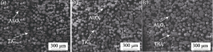
图1
不同样件原材料的SEM形貌
Fig. 1
SEM morphologies of raw materials for different samples
(a) AT10; (b) AT30; (c) AT50
表1 两种原材料粉末的成分及质量分数
Table 1
| Al2O3 | Composition | Al2O3 | SiO2 | Fe2O3 | Na2O | CaO |
|---|---|---|---|---|---|---|
| Content/% | >99.9 | 0.0041 | 0.0021 | 0.0014 | <0.001 | |
| TiCp | Composition | TiCp | Si/Ca | K/Na | Fe | Al |
| Content/% | >99.1 | <0.01 | <0.005 | <0.09 | <0.01 |
1.2 样件制备与检测
成形样件为圆柱结构, 设计尺寸为ϕ5 mm×34 mm, 采用圆弧插补路径进行沉积, 制备样件所用的工艺参数为: 激光功率P=300 W, 扫描速度f=400 mm/min, 送粉速率v=3.8 g/min, z轴提升量Δz=0.4 mm。基板表面的激光光斑尺寸约2 mm。
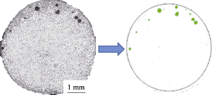
样件制备完成后, 使用240#至3000#金刚石砂盘及2.5 μm粒度金刚石抛磨膏对样件的横、纵截面进行研磨抛光处理, 用于微观组织观察。采用Axioscope 5光学显微镜(OM)以及场发射扫描电镜SU5000(SEM)对抛光后的样件进行图像采集, 并使用EDS进行元素分析。采用XRD-6000型X射线衍射仪(XRD)对原材料粉末以及样件进行物相分析, 扫描范围2θ=0º~100º, 扫描速度为4 (º)/min, 步长为0.04 (°)/step, 靶材为Cu。用排水法测量密度并计算相对密度。利用OM采集成形样件截面的灰度图, 通过图像处理方法可以计算得到孔隙率[25], 按照图2所示用Image-Pro软件统计孔隙占整个截面的比例, 统计时排除狭长状裂纹缺陷, 每种材料比例参数选择3个样件的测量结果取平均值作为气孔率最终结果。
图2
测试样件的力学性能, 包括弯曲强度、显微硬度以及断裂韧性。其中弯曲强度采用三点弯曲法测量, 每个参数制备10个尺寸为35 mm×4 mm×3 mm的长方体试样, 按照公式(1)得到样件弯曲强度[26]:
σf为弯曲强度(MPa); F为最大载荷(N); L为夹具的下跨距, 本实验采用30 mm跨距; b和d分别为试样的宽度和平行于加载方向试样的厚度(mm)。
利用维氏压痕法在抛光后的试样表面测试显微硬度, 施加的负载为9.807 N, 保持时间为15 s。根据公式(2)计算样件的显微硬度[20]:
Hv为维氏硬度值, F表示试验力(N); d表示维氏压痕两对角线算术平均值(mm)。按照裂纹形态将维氏压痕引发的裂纹区分为Palmqvist裂纹和Median裂纹, 并按照公式(3)分别计算5个维氏压痕所对应的断裂韧性值并计算平均值作为样件的断裂韧性[27]。
式中,
图3
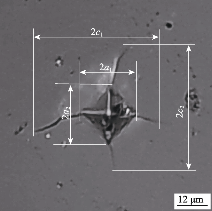
图3
维氏压痕以及断裂韧性计算示意图
Fig. 3
Vickers indentation and fracture toughness calculation diagram
2 结果与讨论
2.1 样件形貌和微观组织
图4(a~c)显示了不同比例AT样件的宏观形貌和光镜放大图像, 样件形状整体上符合预设圆柱形样件, 复合材料样件颜色随着TiCp添加比例的增加逐渐变灰白。AT10陶瓷样件表面可以观察到有规律的凸起与凹陷形成的层间结合特征, 并且样件表面黏附有明显的黄色颗粒。随着TiCp添加量提高, 样件表面黏附颗粒逐渐增多, 层间结合特征不再明显。有部分表面附着的TiCp颗粒在冷却过程中脱离保护气体发生氧化, 随着TiCp添加量增大, 颗粒变为含Ti的白色、淡黄色、橘红色氧化物。
图4
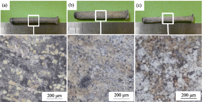
图4
样件外观及放大照片
Fig. 4
Appearances and enlarged images of the samples
(a) AT10; (b) AT30; (c) AT50
图5(a~f)显示了不同含量TiCp复相陶瓷材料的横截面形貌及颗粒分布情况, 白色的TiCp颗粒分布在灰色的连续基体相中, 随着TiCp添加量增大, 基体中TiCp的面积占比明显增大。
图5
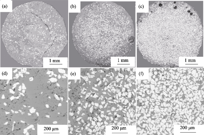
图5
样件横截面全貌以及颗粒分布图
Fig. 5
Full cross-sections and particle distributions of samples
(a-c) Full views of (a) AT10, (b) AT30 and (c) AT50;(d-f) Particle distributions of (d) AT10, (e) AT30 and (f) AT50
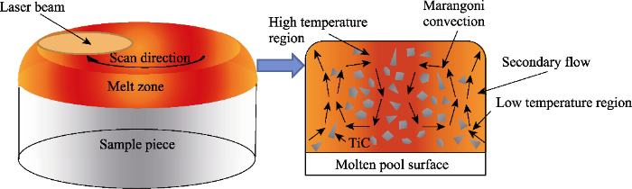
利用Image-Pro软件统计图5横截面内未熔TiCp颗粒面积占总面积之比, 将其视为体积占比并计算实际样件中的成分比例, 可得样件中未熔TiCp颗粒实际质量占比与理论质量占比误差约为0.6%, 可见LDED法成形样件符合预先对复合材料比例的设定。AT30和AT50样件的TiCp颗粒在样件内部相对均匀集中, 但边缘分布相对较少(如图5(b~c)所示)。原因在于第二相颗粒在熔池表面的分布受马兰戈尼对流和二次流驱动[30-31]。如图6所示, LDED成形过程中熔体向四周扩散, 熔池表面的中心温度更高引起剧烈对流, 边缘的流动性有所减弱。在激光循环扫描过程中, 熔池中会形成由边界流向中心的二次流, TiCp颗粒在二次流的作用下从边缘流向中部并在此区域内不停地旋转和重排, 最终使成形样件内部未熔TiCp颗粒分布集中于中心区域。
图6
样件横纵截面微观组织如图7(a~f)所示, 可见连续基体相由主晶相与晶间不连续的白色物相组成。结合横纵截面晶间白色物相的分布特征可以判断, 主晶相由沿沉积高度方向的柱状晶组成。随着TiCp占比提升, 柱状晶边缘的起伏逐渐加剧, 晶间白色物相含量增大且趋向于连续。此外, 柱状晶一次间距随TiCp含量增加而变小, 采用线性截距法测量晶粒尺寸, 得到AT10、AT30、AT50样件基体的晶粒尺寸分别约为24、20、16 μm。这是因为TiC含量增大导致Al2O3含量相对减少, TiC颗粒会阻碍Al2O3晶界迁移, 从而抑制Al2O3晶粒长大[32], 即基体晶粒通过晶界移动而长大的过程中与第二相增强颗粒相遇时, 将形成许多曲率半径很小的新表面, 而增加的新表面提高了体系自由能, 减缓了晶粒自发的长大过程, 阻止了晶粒进一步长大, 从而细化了氧化铝陶瓷晶粒。也有研究发现, 析出物通过钉扎效应减小晶粒尺寸[33]。
图7
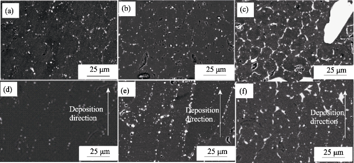
图7
样件微观组织特征
Fig. 7
Microstructures of the sample
(a-c) Cross-sectional images of (a) AT10, (b) AT30 and (c) AT50; (d-f) Longitudinal section images of (d) AT10, (e) AT30 and (f)AT50
图8
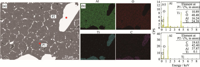
图8
样件横截面EDS分析
Fig. 8
EDS analysis of cross section of sample
(a) Schematic diagram of EDS test area; (b) EDS surface scan; (c) Point scan results
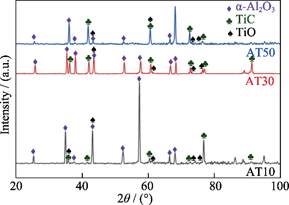
基体中少量C元素和网状分布的白色物相中存在的O元素, 其来源为反应产物中的TiO和仅在高温条件下稳定存在的Al2O, 二者在冷却过程中会进一步反应生成少量的TiOxC1-x和Al2OC等含有Ti和Al成分的碳氧化物[35]。由于晶界上两个晶粒的质点排列取向有一定的差异, 同时晶界结构松散会成为原子快速扩散的通道而引起偏聚, 反应产物以及微量熔化的TiCp就更容易沉淀在晶界。晶粒尺寸也是影响晶界偏析的重要原因, Ishida[36-37]提出晶界偏析与晶粒尺寸之间有一定关系, 较小的晶粒尺寸使晶体内的原子更容易进入晶界区域形成偏聚, 陶瓷材料晶粒尺寸对偏析的影响更甚。随着未熔TiCp颗粒的占比增加, AT样件的晶粒尺寸减小, 基体中会出现更加细密相连的晶界析出相。
图9
2.2 TiCp对裂纹的影响
图10

由上述公式可得, 裂纹的扩展方向切向受拉应力影响, 更容易偏向于TiCp颗粒, 同时对裂纹的偏转效果会随第二相颗粒的尺寸增加而增大。如图11(a)所示, 裂纹扩展至未熔TiCp颗粒处, 此时颗粒与基体结合牢固, 若裂纹扩展能较低, 裂纹则难以贯穿颗粒而被钉扎在TiCp颗粒表面; 如图11(b)所示, 裂纹直接贯穿未熔的TiCp颗粒继续向前扩展, 此时裂纹扩展会消耗更多的能量。随着裂纹扩展能的减弱, 遇到未熔的TiCp颗粒不足以贯穿其中时就会发生偏转, 绕过TiCp颗粒继续向前扩展, 裂纹偏转增加了新表面的面积。贯穿强化颗粒和引起裂纹偏转都可以达到消耗扩展能, 进而抑制裂纹的效果。AT30和AT50样件中Al2O3基体的晶粒尺寸更小, 越有利于减小初始裂纹尺寸, 在成形的冷却阶段两种材料的热膨胀失配会使TiCp颗粒受到Al2O3基体的压应力作用, TiCp颗粒周围的基体材料承受的拉应力, 使基体材料未熔TiCp颗粒附近产生显微裂纹, 如图11(a)所示。弥散分布的微裂纹会促使导致断裂的主裂纹在扩展过程中分岔, 导致主裂纹扩展路径曲折不平,而增加扩展过程中的表面能。当残余应力达到晶界张应力或剪切应力时, 则可能沿晶界形成微裂纹, 尺寸较小的裂纹可以吸收一部分裂纹扩展的能量以减小可能出现的更大宏观裂纹, 从而使裂纹快速扩展受到阻碍[41-42]。材料基体中未熔TiCp颗粒含量越高, 越有利于其分布在裂纹扩展路径上, 消耗更多的裂纹扩展能并更好地抑制裂纹扩展。因此AT30和AT50复相陶瓷材料对裂纹抑制作用明显, 没有出现显著的宏观裂纹。
图11
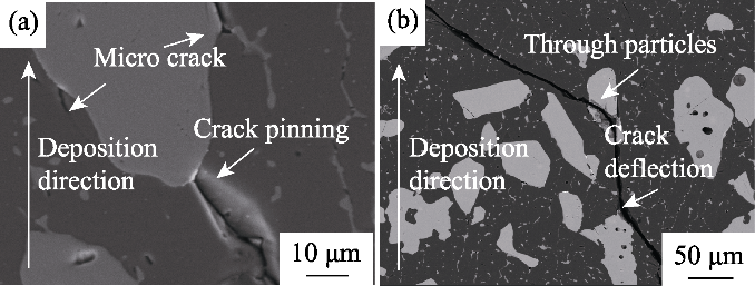
图11
TiCp颗粒对裂纹扩展的偏转和阻碍作用
Fig. 11
Deflection and obstruction effects of TiC particles on crack growth
(a) Pinning and micro crack; (b) Through particles and crack deflection
2.3 TiCp对相对密度的影响
烧结陶瓷过程中使用的黏结剂是影响最终成品相对密度的重要原因之一, 陶瓷材料中的孔隙会降低陶瓷的力学性能, 在成形过程中形成裂纹源并造成开裂[43-44]。快速制备无黏结剂的陶瓷材料是陶瓷激光定向能量沉积技术的主要优势。激光定向能量沉积作为直接经历熔化到凝固的成形技术, 可以赋予材料独特的孔隙情况。如图5(a~c)展示出的AT复相陶瓷样件横截面孔隙缺陷的分布特征, AT10样件内部有少量小孔隙, AT30样件没有明显孔隙缺陷, AT50靠近边界处出现较大孔隙。测试相对密度和气孔率与TiCp掺杂比例的关系, 结果如图12(a~b)所示, 计算气孔率时已排除样件内部的狭长缺陷(如图5中明显的裂痕缺陷), 因此表征TiCp颗粒含量增大对排除气体的作用时, 气孔率和相对密度二者相加不等于100%。
图12
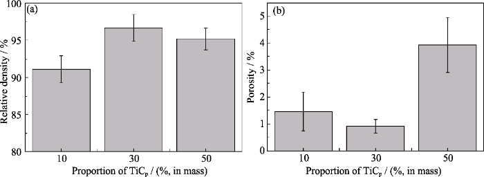
图12
样件的致密性
Fig. 12
Compactness of the samples
(a) Relative density; (b) Porosity
AT10基体中的TiCp颗粒过少对裂纹无明显抑制作用, 未熔颗粒的搅拌作用较弱也无法有效排除反应气体, 少量气孔和大量裂纹使得AT10的相对密度最差, 气孔率为1.47%的情况下, 相对密度为91.09%。AT30相对密度最高(96.64%)原因在于更多的TiCp有效抑制了裂纹, 充足的Al2O3在高温下熔化使熔池流动性相对较好。虽然生成气体的反应依然存在(气孔率0.92%), 但是相比于AT10加入了更多的不规则TiCp颗粒, 强化了陶瓷成形过程中对熔池的搅拌作用, 加速气体逸出, 使得气孔率降低。而由于相同条件下TiCp熔点比Al2O3高1000 ℃以上, AT50复合材料熔池中熔化的成分减少, 熔池流动性减弱, 大量不规则的未熔TiCp颗粒在低流动性的熔池中无法充分流动。同时, 相同工艺参数下材料反应生成的气体增加, 液相又无法及时补足, 导致不能排除基体中的气体, 使AT50的样件存在如图5(c)所示的肉眼可见大型孔洞, 使其气孔率高达3.94%, 相对密度只有95.17%。
2.4 TiCp比例对样件力学性能的影响
图13
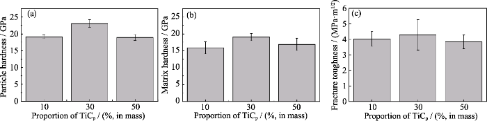
图13
不同比例AT样件的力学性能
Fig. 13
Mechanical properties of AT-samples of different proportions
(a) Microhardness of particles; (b) Matrix microhardness; (c) Fracture toughness
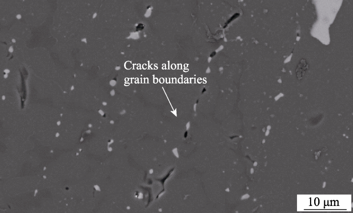
断裂韧性在陶瓷材料的应用中也是值得关注的重要性能, 图13(c)展示了AT复相陶瓷断裂韧性情况。相比于AT10样件, AT30样件由于细化晶粒和颗粒强化两者共同作用, 阻碍裂纹扩展的能力较强, 有效地消耗了裂纹扩展能并抑制了裂纹扩展, 增加了位错运动进行的难度进而达到更强的断裂强度[47]。AT50样件的晶粒虽然比AT30更小, 未熔颗粒更多, 但是严重的气孔缺陷以及更多的晶界析出物使其晶间结合疏松, 如图14所示细微裂纹容易沿晶界扩展, 因此对裂纹的阻碍能力相对较弱。AT30材料没有明显缺陷, 断裂韧性最佳达4.29 MPa·m1/2, 已达到同种材料的传统烧结水平(4.5 MPa·m1/2), 与LDED制备的纯Al2O3的断裂韧性(3.55 MPa·m1/2)[46]相比, 提升了20.85%。
图14
式中, σf为弯曲强度; E为弹性模量; γf为断裂表面能, 可用于描述样件中裂纹扩展单位面积消耗的能量; a为裂纹尺寸。可以发现样件的内部裂纹尺寸、弹性模量以及断裂表面能是影响弯曲强度的三个因素。
图15
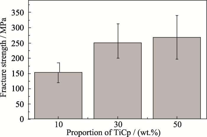
图15
不同TiCp比例AT样件弯曲强度
Fig. 15
Fracture strength of different TiCp proportions AT samples
AT10内部肉眼可见的宏观裂纹和少量气孔, 增大了材料的裂纹尺寸, 极大地降低了弯曲性能。TiCp颗粒的弹性模量大于Al2O3基体, 复合样件的弹性模量会随着TiCp含量增大而增大, 从公式(9)可以看出弹性模量增大会提高复合样件的弯曲强度。且随着TiCp掺杂量增大, 更多的未熔TiCp颗粒增大了裂纹扩展能。根据公式(10)[49], 计算TiCp不同掺杂比例复合样件的断裂表面能
式中, d0为晶粒尺寸,
3 结论
研究利用LDED技术制备了不同TiCp掺杂比例(10%~50%, 质量分数)的AT复相陶瓷样件, 重点研究了不同比例TiCp掺杂对样件裂纹、气孔缺陷、力学性能的影响规律及作用机理。主要研究结论如下:
1) 未熔TiCp颗粒由于马兰戈尼效应呈现外疏里密的分布特征。微观形貌上, 随着TiCp含量的增加, 晶粒尺寸逐渐减小。晶粒尺寸越小, 导致晶间析出物越多, 并且缺陷尺寸越小。
2) TiCp掺杂引起的裂纹钉扎、穿颗粒和偏转等效应, 有效抑制了裂纹在样件基体内的扩展。TiCp含量越大, 对裂纹的抑制越显著, 30%以上比例时不形成明显裂纹。
3) AT10样件由于内部存在较大的裂纹, 严重影响了材料的致密性, 因此AT10样件的相对密度最低; AT50样件存在大量的气孔,相对密度也有所降低; 而AT30样件由于避免了裂纹与气孔问题, 因此具有最高的相对密度。
4) 样件力学性能受缺陷分布和晶粒尺寸的影响较大。裂纹、气孔和晶间析出物对材料性能有削弱作用。AT30样件性能最佳, 相对密度为96.64%, 显微硬度和断裂韧性分别达到21.07 GPa和4.29 MPa·m1/2。
本研究实现了高性能熔体自生AT陶瓷的LDED直接增材制造, 为其组织及性能的控制提供了必要的理论和技术指导, 也为熔体自生AT陶瓷的低成本、高效率、快速制造提供了新的方案。
参考文献
Al2O3/TiC based metal cutting tools by microwave sintering followed by hot isostatic pressing
Toughening of brittle solids by martensitic transformations
Preparation, microstructures and properties of Al2O3-TiC composites
Effect of SiC addition to Al2O3 ceramics used in cutting tools

In this study, the effect of the addition of silicon carbide to alumina ceramics commonly used in cutting tool applications is addressed. Performance of Al2O3–SiC composite cutting inserts during the machining of hardened steels and ductile iron was compared to the results obtained for a cutting tool made out of 99 wt.% Al2O3, Al2O3–TiC, Al2O3–TiC–ZrO2, and Al2O3–TiN. In almost all tests, the composite with silicon carbide demonstrated better wear resistance, longer tool lifetime, and the ability to cut at higher speeds. The enhanced properties of cutting tools with SiC can be attributed to the morphology and dimensions of the inclusions in the matrix as well as to the strength of the interphase boundaries, small porosity, and lack of high inner stresses in the volume.
Structure formation in the combustion synthesis of Al2O3/TiC composites
Direct additive manufacturing of TiCp reinforced Al2O3-ZrO2 eutectic functionally graded ceramics by laser directed energy deposition
Research progress on ultrahigh temperature oxide eutectic ceramics by laser additive manufacturing
Melt-grown oxide eutectic ceramics possess a large area of clean and firmly bonded phase interfaces through liquid-solid phase transformation, which makes them present excellent high-temperature properties such as strength retention, creep resistance, thermal stability, oxidation and corrosion resistance. As a result, directionally solidified oxide eutectic composite ceramics have been regarded as one of candidates for new generation of high temperature structural materials which can service above 1400 ℃ in oxidation environment for a long period. In recent years, laser additive manufacturing based on melt growth has developed into the most promising technique for preparing ultrahigh-temperature oxide eutectic ceramics due to its unique advantage in one-step fabricating highly dense parts with large sample size and complex shape. In this paper, laser additive manufacturing technology was summarized in terms of forming principle, technical features and classification. The research status and the encountered technical problems in additively manufacturing melt-grown oxide eutectic ceramics were reviewed. Moreover, the research progress on laser additive manufacturing oxide eutectic ceramics was introduced from the aspects of laser forming process, solidification defect control, solidification microstructure evolution, and mechanical properties. Finally, the key bottlenecks of realizing engineering applications of the laser 3D-printed oxide eutectic ceramics were pointed out, and the future development directions of this field were prospected. The focus of the future work can be summarized into four points: developing high-quality spherical eutectic ceramic powders, preparing large-scale eutectic parts with complex shapes, accurate controlling solidification defects, as well as strengthening and toughening eutectic composites.
Synchronous-hammer-forging- assisted laser directed energy deposition additive manufacturing of high-performance 316L samples
Direct additive manufacturing of melt growth Al2O3-ZrO2 functionally graded ceramics by laser directed energy deposition
Process optimization of melt growth alumina/aluminum titanate composites directed energy deposition: effects of scanning speed
Shaping quality, microstructure, and mechanical properties of melt-grown mullite ceramics by directed laser deposition
Rapid growth and formation mechanism of ultrafine structural oxide eutectic ceramics by laser direct forming
Heat treatment of melt-grown alumina ceramics with trace glass fabricated by laser directed energy deposition
Investigation of melt-growth alumina/aluminum titanate composite ceramics prepared by directed energy deposition
Advances in 3D printing of magnetic materials: fabrication, properties, and their applications
Magnetic materials are of increasing importance for many essential applications due to their unique magnetic properties. However, due to the limited fabrication ability, magnetic materials are restricted by simple geometric shapes. Three-dimensional (3D) printing is a highly versatile technique that can be utilized for constructing magnetic materials. The shape flexibility of magnets unleashes opportunities for magnetic composites with reducing post-manufacturing costs, motivating the review on 3D printing of magnetic materials. This paper focuses on recent achievements of magnetic materials using 3D printing technologies, followed by the characterization of their magnetic properties, which are further enhanced by modification. Interestingly, the corresponding properties depend on the intrinsic nature of starting materials, 3D printing processing parameters, and the optimized structural design. More emphasis is placed on the functional applications of 3D-printed magnetic materials in different fields. Lastly, the current challenges and future opportunities are also addressed.
Ueber die beziehung zwischen den beiden elasticitätsconstanten isotroper körper
Berechnung der fleissgrenze von mischkristallen auf grund der plastizitats bedingung für einkrisalle
Molten pool behaviour and its physical mechanism during selective laser melting of TiC/AlSi10Mg nanocomposites: simulation and experiments
Particulate migration behavior and its mechanism during selective laser melting of TiC reinforced Al matrix nanocomposites
TiC含量对无压烧结TiC-Al2O3导电陶瓷复合材料微观结构与性能的影响
以Al<sub>2</sub>O<sub>3</sub>、TiC粉体为原料,采用无压烧结技术制备了TiC-Al<sub>2</sub>O<sub>3</sub>导电陶瓷复合材料,研究了TiC体积分数(30%~45%)对陶瓷复合材料微观结构和性能的影响。结果表明:TiC-Al<sub>2</sub>O<sub>3</sub>导电陶瓷复合材料主要由Al<sub>2</sub>O<sub>3</sub>和TiC两相组成;随着TiC含量的增加,陶瓷复合材料的相对密度降低,开口气孔率增大,当TiC体积分数为30%时,相对密度最大,开口气孔率最低,分别为95.5%和3.0%;陶瓷复合材料中导电相TiC均连接为网状结构,随着TiC含量的增加,TiC所形成的网状结构越发完整,陶瓷复合材料的硬度先升高后降低,电阻率和断裂韧度均呈降低趋势,抗弯强度增大;当TiC体积分数为45%时,陶瓷复合材料的抗弯强度最高,电阻率最低,分别为361 MPa和6.95×10<sup>-6</sup> Ω·m。
A model of grain boundary complexion transitions and grain growth in yttria-doped alumina
Pressureless sintering of alumina-titanium carbide composites
Effect of grain size on grain boundary segregation
Size-dependent solute segregation and total solubility in ultrafine polycrystals: Ca in TiO2
Process optimization for suppressing cracks in laser engineered net shaping of Al2O3 ceramics
One-step additive manufacturing of TiCp reinforced Al2O3-ZrO2 eutectic ceramics composites by laser directed energy deposition
The Exploration on new approach of strengthening and toughening of ceramic materials
Microcomputed tomography analysis of intralayer porosity generation in laser direct metal deposition and its causes
The effect of laser power and traverse speed on microstructure, porosity, and build height in laser-deposited Ti6A14V
Quantitative characterization of porosity in stainless steel LENS powders and deposits
Microstructure and macro properties of Al2O3 ceramics prepared by laser engineered net shaping
Growth of Al2O3/ZrO2(Y2O3) eutectic rods by the laser floating zone technique: effect of the rotation
Effects of TiO2 doping on microstructure and properties of directed laser deposition alumina/ aluminum titanate composites
Microstructure and mechanical properties of melt-grown alumina-mullite/glass composites fabricated by directed laser deposition
Melt-grown alumina-based composites are receiving increasing attention due to their potential for aerospace applications; however, the rapid preparation of high-performance components remains a challenge. Herein, a novel route for 3D printing dense (< 99.4%) high-performance melt-grown alumina-mullite/glass composites using directed laser deposition (DLD) is proposed. Key issues on the composites, including phase composition, microstructure formation/evolution, densification, and mechanical properties, are systematically investigated. The toughening and strengthening mechanisms are analyzed using classical fracture mechanics, Griffith strength theory, and solid/glass interface infiltration theory. It is demonstrated that the composites are composed of corundum, mullite, and glass, or corundum and glass. With the increase of alumina content in the initial powder, corundum grains gradually evolve from near-equiaxed dendrite to columnar dendrite and cellular structures due to the weakening of constitutional undercooling and small nucleation undercooling. The microhardness and fracture toughness are the highest at 92.5 mol% alumina, with 18.39±0.38 GPa and 3.07±0.13 MPa·m1/2, respectively. The maximum strength is 310.1±36.5 MPa at 95 mol% alumina. Strength enhancement is attributed to the improved densification due to the trace silica doping and the relief of residual stresses. The method unravels the potential of preparing dense high-performance melt-grown alumina-based composites by the DLD technology.
The cleavage strength of polycrystals
The deformation and ageing of mild steel: III discussion of results
