

反应连接法是将熔融硅渗入含有SiC和碳粉的多孔碳素坯中, 在1450~1700 ℃发生Si-C反应形成新的SiC。与其他方法相比, 反应连接法可以设计中间层以匹配连接材料的热机械性能。Singh等[9-10]系统探讨了材料成分和工艺过程对反应连接法得到的接头的连接性能的影响机理。Luo等[12]使用SiC/C流延膜通过Si-C反应连接法连接SiC陶瓷, 实现了连接层厚度的精准调控。但目前反应连接法使用的多孔碳素坯碳源多为固体粉末, 如碳粉、石墨和焦油[10], 固体碳源会让反应连接过程变得复杂和难以控制, 主要体现在两个方面: (1)难以获得均匀分布的多孔碳生坯; (2)难以获得低黏度的高固含量浆料。高温下熔融硅的充分渗透与孔结构关系密切, 是获得稳定连接的重要因素。研究表明, 可以用有机树脂代替石墨粉作为碳源, 通过聚合诱导相分离方法获得均匀的多孔碳[13]。酚醛树脂具有碳收率高、附着力好等优点, 具有作为碳源的潜力。
1 实验方法
1.1 实验原料
研究所用的基体材料为Cf/SiC复合材料, 由实验室自制, 密度为(2.77±0.03) g/cm3, 常温弯曲强度为129~241 MPa。使用热固性酚醛树脂(PF, 工业级)作为碳源, 乙二醇(EG, AR)作为有机溶剂, 氯化亚铁(FeCl2, AR>98.0%)和硼酸(H3BO3, GR>99.8%)作为成孔剂, α-SiC粉末(SIKA, 0.5 μm)作为惰性填料, 聚乙烯吡咯烷酮(K-30, AR)作为分散剂。
1.2 制备及连接过程
配制连接层所用树脂基浆料: (a)将有机溶剂、酚醛树脂、成孔剂混合, 搅拌使之充分溶解, 得到树脂基溶液; (b)将碳化硅微粉、分散剂与树脂基溶液混合, 使用聚氨酯球磨罐和SiC陶瓷球对浆料球磨6 h后, 取出浆料静置并抽真空除去气泡, 得到连接用树脂基浆料。
基体材料的处理: 放置于酒精中超声清洗20 min, 干燥后待用。在基体材料之间涂覆树脂基浆料, 使用石墨模具夹紧并在80~120 ℃保温8 h, 升温至200 ℃再保温6 h。之后放置于900 ℃真空炉中碳化, 使连接层中的树脂基溶液或浆料裂解为多孔碳素坯。冷却后取出, 将样品埋入硅粉, 真空条件下在1600 ℃反应30 min。
1.3 材料表征
采用X射线衍射仪(XRD, D/Max-2250V)分析物相组成。使用场发射扫描电子显微镜(SEM, SU-8220, Hitachi, 日本)分析样品微观结构。采用Instron5566系统测试连接样品的抗弯强度。强度保留率为连接件抗弯强度与同批次基体材料抗弯强度的比值。通过HF-HNO3(1 : 1配比)混合酸中蚀刻16 h的质量损失计算得到游离硅含量。
2 结果与讨论
2.1 多孔碳素坯密度对连接样品微观结构与性能的影响
实现碳与熔融硅完全反应生成碳化硅且无游离硅残留的多孔碳素坯理论密度为0.963 g·cm-3[17]。但硅碳反应过程中新生成的碳化硅将堵塞渗Si通道, 无法保证在理论密度下实现碳与液相Si完全反应。因此, 需要控制多孔碳素坯的密度低于理论密度。本研究探讨了不同密度(0.31、0.51、0.70和0.90 g·cm-3)的多孔碳素坯对连接性能的影响规律。
不同密度的多孔碳素坯连接试样微观结构如图1(a~c)所示, 灰色区域为SiC, 黑色相为碳纤维, 白色区域为游离硅相, 连接层厚度范围大约为10~20 μm, 连接层中未发现残留碳, 说明多孔碳素坯中的碳全部与熔融硅反应生成碳化硅。随着多孔碳素坯密度增加, 硅连接层中白色区域逐渐减少, 说明游离硅含量明显下降。如图1(d)所示, 连接后样品的抗弯强度随着多孔碳素坯密度的增加而增大。多孔碳密度较低孔隙率势必更高, 这使得反应完成后生成的SiC无法有效填充孔隙, 熔融硅填充这些孔隙后留下大块游离硅, 这是其力学性能较差的原因; 增加碳素坯密度, 降低孔隙率, 可明显降低游离硅含量, 提高连接性能。所测复合材料连接件均在接头处断裂。因此, 多孔碳素坯的密度在0.71~0.90 g·cm-3范围较为合适。
图1
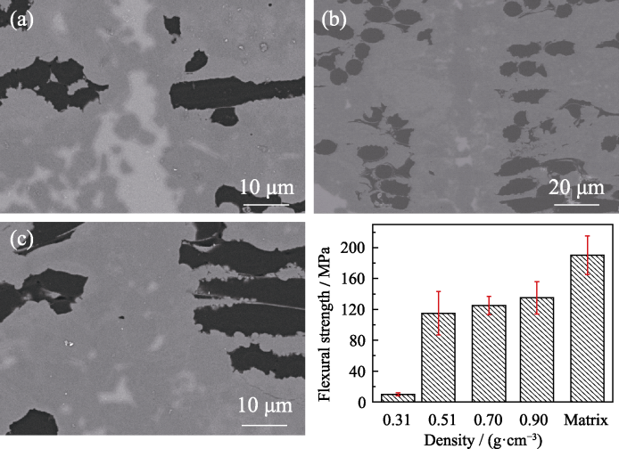
图1
不同体积密度碳素坯((a)0.51, (b)0.70, (c)0.90)接头微观结构, (d)连接样品力学性能
Fig. 1
Microstructures of joints with different volumn densities ((a) 0.51, (b) 0.70, (b) 0.90) and (d) flexural strengths of the joined specimens
2.2 多孔碳素坯孔径对连接接头微观结构与性能的影响
表1 树脂溶液组成及裂解后多孔碳素坯性能参数
Table 1
| Sample | PF/% | EG/% | Pore former* | Residual carbon**/% | Average pore size/nm | Bulk density/(g·cm-3) |
|---|---|---|---|---|---|---|
| 1 | 50 | 50 | FeCl2 (1%) | 23+1.1 | 190±15 | 0.73±0.01 |
| 2 | 50 | 50 | H3BO3 (1.5%) | 24.3±0.9 | 642±15 | 0.74±0.01 |
| 3 | 50 | 50 | FeCl2 (1%) + H3BO3 (1.5%) | 24.1±1.7 | 1226±48 | 0.74±0.03 |
| 4 | 50 | 50 | H3BO3 (2.5%) | 25.8±2.1 | 1552±38 | 0.79±0.03 |
| 5 | 50 | 50 | H3BO3 (3.5%) | 26.7±1.5 | 2363±54 | 0.79±0.03 |
* represents the additional content of the total weight of EG and PF (in mass)
** represents the residual carbon content of the resin solution (in mass)
为了研究不同孔径多孔碳素坯硅融渗过程, 先利用多孔碳素坯在高温下融渗液相硅制备反应烧结SiC样品。图2(a~e)所示为五种孔径的多孔碳素坯所制备的反应烧结碳化硅样品的表面微观形貌, 其中白色区域为Si相, 灰色区域为SiC, 黑色区域为C。当孔径较小时(图2(a~c)), 样品基本致密, 没有气孔和残留碳等, 熔融Si与C完全反应。当孔径增大至1552 nm时, 样品中出现气孔且分布在碳化硅相中, 这是由于熔融硅渗入后与碳反应生成SiC堵塞了渗透通道, 液相硅无法填充孔隙。随着孔径继续增大到2363 nm, 样品出现大量孔洞和未反应的残留碳, 说明液相Si未能完全与C浸渍, 主要原因是孔径增大, 减小了毛细管力, 降低了渗透速率, 从而在熔融硅还未完全浸渍多孔碳素坯时, 新生成的碳化硅堵塞了熔融硅的渗透通道。样品表面通过HF-HNO3混合酸进行游离硅腐蚀, 游离硅去除后在样品表面留下了孔洞(图2(f~j)所示), 可以通过孔洞大小来表征样品中游离硅尺寸。很明显, 随着多孔碳素坯孔径增大, 游离硅尺寸逐渐增大。
图2
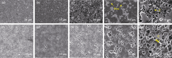
图2
HF-HNO3腐蚀前后不同孔径碳素坯制备反应烧结碳化硅陶瓷表面微观形貌
Fig. 2
Morphologies of the polished surfaces before and after HF-HNO3 corrosion of RBSC fabricated from preforms with different pore sizes
(a, f) 190 nm; (b, g) 642 nm; (c, h) 1226 nm; (d, i) 1552 nm; (e, j) 2363 nm
图3所示为不同孔径多孔碳素坯在1600 ℃渗硅后烧结体的XRD图谱, 当孔径小于2363 nm时, 样品主要由Si和β-SiC相组成, 随孔径增大, 硅峰相对强度变化不大。当孔径在2363 nm时, 出现石墨特征峰, 说明存在碳残留。熔融硅与碳反应是放热过程, 局部温度可达到2000 ℃以上, 导致残留碳石墨化。不同孔径多孔碳素坯制备的反应烧结碳化硅的性能参数如表2所示, 从表中可以看出, 游离硅含量变化不大, 意味着游离硅含量与孔径大小无关。样品弯曲强度在孔径为190 nm时达到最大, 即(296±28) MPa。弯曲强度随多孔碳素坯孔径的增加而减小, 原因在于游离硅尺寸越小, 力学性能越优异[21]。当孔径较大时(2363 nm), 由于存在残留碳和大量孔洞, 弯曲强度大幅度下降。
图3
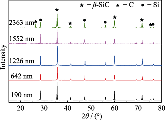
图3
不同孔径多孔碳素坯反应烧结样品的XRD图谱
Fig. 3
XRD patterns of the RBSC fabricated from preforms with different pore sizes
表2 不同孔径的多孔碳素坯反应烧结样品性能
Table 2
| Pore size/nm | Open porosity/% | Density/ (g·cm-3) | Flexural strength/MPa | Residual Si/(%, in volume) |
|---|---|---|---|---|
| 190 | 0.97 | 2.93 | 296±28 | 16 |
| 642 | 1.26 | 2.91 | 268±46 | 14 |
| 1226 | 1.87 | 2.88 | 248±22 | 16 |
| 1552 | 3.51 | 2.81 | 238±44 | 12 |
| 2363 | 18.76 | 2.10 | 115±32 | 13 |
不同孔径的多孔碳素坯作为连接材料所得的连接试样表面经HF-HNO3腐蚀后的微观结构如图4所示。连接层中碳化硅相表现为灰色, 碳纤维表现为黑色, 其中孔洞主要为游离硅被HF-HNO3腐蚀所致。孔径为14 nm时, 熔融硅更易发生堵塞, 在连接层核心区域留下更多孔洞(图4(a))。连接层中新生成的SiC颗粒随着孔径增大而增大, 腐蚀后留下的孔洞也显示出游离硅尺寸随孔径的增大而增大。当孔径增大至1226 nm时, 连接层中心区域留下的孔洞较大(图4(e)), 说明反应后生成游离硅尺寸过大, 这将极大地影响连接性能。表3给出了不同孔径多孔碳素坯连接件接头的弯曲强度, 样品弯曲强度在孔径为190 nm时达到最大, 即(125±12) MPa, 所测复合材料连接件均在接头处断裂。孔径过小和过大都会降低连接性能。
图4
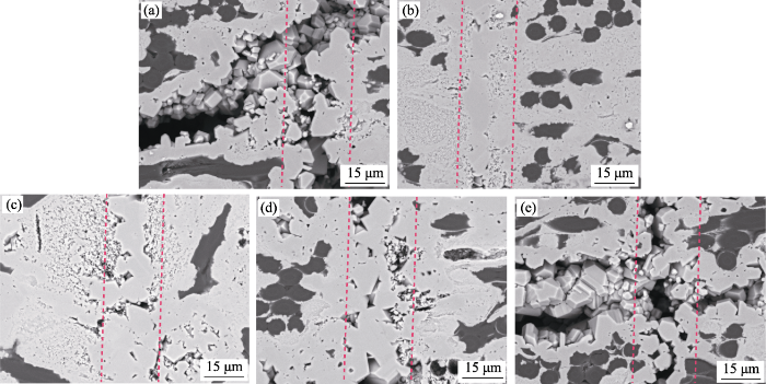
图4
HF-HNO3腐蚀后不同孔径多孔碳素坯连接样品表面形貌
Fig. 4
Surface microstructures after HF-HNO3 corrosion of joining samples with different pore sizes
(a) 14 nm; (b) 190 nm; (c) 316 nm; (d) 642 nm; (e) 1226 nm
表3 不同孔径连接样品力学性能
Table 3
| Pore size/nm | Flexural strength/MPa | Strength retention/% |
|---|---|---|
| 14 | 90±28 | 61 |
| 190 | 125±12 | 85 |
| 316 | 77±10 | 52 |
| 642 | 107±15 | 73 |
| 1226 | 65±22 | 44 |
2.3 惰性填料对接头微观结构和力学性能的影响
表4 树脂基浆料组成
Table 4
| Sample | PF/ % | EG/ % | Dispersant*/% | Pore former** (FeCl2)/% | α-SiC powder/% |
|---|---|---|---|---|---|
| 1 | 40 | 40 | 4 | 1 | 20 |
| 2 | 35 | 35 | 4 | 1 | 30 |
| 3 | 30 | 30 | 4 | 1 | 40 |
| 4 | 25 | 25 | 4 | 1 | 50 |
| 5 | 22.5 | 22.5 | 4 | 1 | 55 |
* represents the additional content of the total weight of EG, PF and α-SiC powder (in mass)
**represents the additional content of the total weight of EG and PF (in mass)
图5
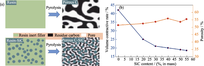
图5
(a)惰性填料添加后作用示意图和(b)多孔碳素坯的体积收缩和孔隙率变化曲线
Fig. 5
(a) Schematic of the action of inert filler and (b) volume shrinkage and porosity change curves of porous carbon blanks
图6
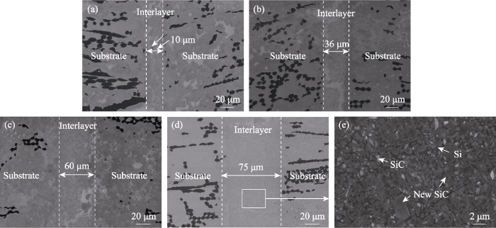
图6
不同含量((a) 30%; (b) 40%; (c) 50%; (d) 55%, 质量分数)惰性填料连接件表面微观结构及(e)图(d)的局部放大图
Fig. 6
Microstructures of the joint with different contents of inert filler ((a) 30%; (b) 40%; (c) 50%; (d) 55%, in mass) and (e) partial enlargement of (d)
图7
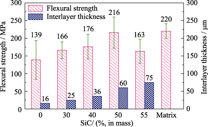
图7
不同含量惰性填料连接件的力学性能
Fig. 7
Flexural strength of the joined samples with different contents of inert filler
3 结论
使用酚醛树脂作为碳源实现了Cf/SiC复合材料的稳定连接, 并研究了多孔碳素坯体积密度、孔径以及惰性填料含量对接头连接性能和微观结构的影响。主要结论如下:
1) 多孔碳素坯的体积密度范围在0.71~0.90 g·cm-3比较适宜。连接层中游离Si含量随多孔碳素坯体积密度的增加逐渐下降, 性能更优。
2) 多孔碳素坯的孔径范围在200~600 nm比较适宜, 随着孔径增大, 游离硅尺寸逐渐增大。平均孔径在190 nm时, 连接件的弯曲强度最大达(125±12) MPa。
3) SiC惰性填料有利于减小多孔碳素坯的体积收缩, 当SiC质量分数为50%时, 连接件弯曲强度达到(216±44) MPa, 基本与基体材料强度相当。
参考文献
Tensile properties of two-dimensional carbon fiber reinforced silicon carbide composites at temperatures up to 2300 ℃
Thermal cycling behavior of bi-layer Yb2Si2O7/SiC EBC coated Cf/SiC composites in burner rig tests
Transverse thermal conductivity of thin C/SiC composites fabricated by slurry infiltration and pyrolysis
High temperature flexural properties of SiBC modified C/SiC composites
Microstructure of reaction layer and its effect on the joining strength of SiC/SiC joints brazed using Ag-Cu-In-Ti alloy
Joining dental ceramic layers with glass

Test the hypothesis that glass-bonding of free-form veneer and core ceramic layers can produce robust interfaces, chemically durable and esthetic in appearance and, above all, resistant to delamination.Layers of independently produced porcelains (NobelRondo™ Press porcelain, Nobel BioCare AB and Sagkura Interaction porcelain, Elephant Dental) and matching alumina or zirconia core ceramics (Procera alumina, Nobel BioCare AB, BioZyram yttria stabilized tetragonal zirconia polycrystal, Cyrtina Dental) were joined with designed glasses, tailored to match thermal expansion coefficients of the components and free of toxic elements. Scanning electron microprobe analysis was used to characterize the chemistry of the joined interfaces, specifically to confirm interdiffusion of ions. Vickers indentations were used to drive controlled corner cracks into the glass interlayers to evaluate the toughness of the interfaces.The glass-bonded interfaces were found to have robust integrity relative to interfaces fused without glass, or those fused with a resin-based adhesive.The structural integrity of the interfaces between porcelain veneers and alumina or zirconia cores is a critical factor in the longevity of all-ceramic dental crowns and fixed dental prostheses.Copyright © 2011 Academy of Dental Materials. All rights reserved.
Thickness-dependent phase evolution and bonding strength of SiC ceramics joints with active Ti interlayer
Joining of SiCf/SiC using polycarbosilane and polysilazane preceramic mixtures
Design, fabrication, and testing of ceramic joints for high temperature SiC/SiC composites
Microstructure and mechanical properties of reaction- formed joints in reaction-bonded silicon carbide ceramics
Reaction forming of joints in silicon carbide ceramic materials
Development of SiC-SiC joint by reaction bonding method using SiC/C tapes as the interlayer
Gelcasting of silicon carbide ceramics using phenolic resin and furfuryl alcohol as the gel former
Effect of FeCl2 on the pore structure of porous carbon obtained from phenol formaldehyde resin and ethylene glycol
Pore structure control of porous carbon obtained from phenol formaldehyde resin and ethylene glycol: the effect of H3BO3 on the pore structure
Pore structure control of porous carbon via the synergistic effect of boric acid and divalent metal iron salt
Effect of carbon preform pore volume and infiltrants on the composition of reaction-formed silicon carbide materials
The effect of porous carbon preform and the infiltration process on the properties of reaction-formed SiC
Melt infiltration approach to ceramic matrix composites
Microstructure evolution and reaction mechanism of microporous carbon derived SiC ceramic
