王勇 , 于云, 冯爱虎
WANG Yong, YU Yun, FENG Ai-Hu
中图分类号: O613
文献标识码: A
文章编号: 1000-324X(2018)04-0469-06
通讯作者:
收稿日期: 2017-04-10
网络出版日期: 2018-04-30
版权声明: 2018 无机材料学报编委会 This is an open-access article distributed under the terms of the Creative Commons Attribution License, which permits unrestricted use, distribution, and reproduction in any medium, provided the original author and source are credited.
展开
摘要
通过溶胶-凝胶法制备了孔径小于1 μm的多级孔径新型石墨烯气凝胶。制备过程中, 首先通过Nafion对氧化石墨烯(GO)表面进行化学修饰, 并利用乙二胺还原制备石墨烯水凝胶, 最终通过冷冻干燥形成石墨烯气凝胶。实验发现Nafion可以有效减少制备过程中氧化石墨烯的团聚, 使石墨烯气凝胶形成多级孔径形貌。所得石墨烯气凝胶的孔径可控制在1 μm以内, 远小于传统石墨烯气凝胶材料的孔径(20~100 μm)。这种具有独特结构的石墨烯气凝胶表现出优异的性能, 例如高比表面积, 高孔隙率, 其电化学电容性能相对传统气凝胶提高了约40%。
关键词:
Abstract
A novel graphene aerogel with pore size less than 1 µm was synthesized by Sol-Gel method, in which Nafion was skillfully introduced as modifiers connecting graphene oxides (GO). Ethylenediamine was used to produce a chemically linked graphene hydrogel during reducing process, which can then be freeze-dried to remove the absorbed water to form graphene aerogel. Nafion in GO solution prohibits the re-stacking of individual graphene sheets during reduction and freeze-drying process. By the above method, the pore size of as-prepared graphene aerogel could be effectively controlled within 1 µm, much less than that of the traditional graphene aerogel (20- 100 µm). The new graphene aerogel with unique structure exhibited excellent properties, such as high specific surface area, high porosity, and better electrochemical properties. All data suggest that this graphene aerogel may have promising application prospect in the field of energy.
Keywords:
Graphene is a two-dimensional material composed of only one layer carbon atoms, which are sp2-bonded in a planar hexagonal structure[1]. This special structure endorses graphene many outstanding properties, such as good transparency[2], large specific surface area[3], great thermal[4,5] and electrical conductivity[6], and good mechanical properties and chemical stability[7]. Graphene has been widely used in the area of composite materials[8], energy[9] and other fields for these properties.
Although graphene is stable once prepared, the planar structure introduces strong Van der Waals forces when the distance of different graphene sheets is close enough. The outstanding properties of single layer graphene would be seriously damaged when this nano material was agglomerated. It is difficult to reverse the agglomeration because of the strong π - π interaction between graphene layers[10]. Thus, the most important challenge in the research and application of graphene is maintaining graphene in single layer state. Graphene aerogel is a graphene derivative with three dimensional porous structures. This structure effectively constrains the agglomeration of graphene and extend the application of planar graphene to more areas like Li battery[11] and supercapacitors[9].
The preparation of graphene aerogel is generally divided into two categories, direct fabrication with pristine graphene through template methods[12], or the self-assembling of graphene oxide (GO) dispersion[13]. Fabrication with pristine graphene was limited by special template materials and CVD equipments[13]. Fabricating graphene aerogel through GO way was more favorable, as it can be prepared in a large scale through liquid phase reaction. The oxygen containing groups (-OH, -O-, -COOH) connected on the basal plane of GO make it possible to be dispersed in water stably without other surfactants. Also GOcould be restored to planar hexagonal structure by the reduction with different agents[14]. However, it is still difficult to prepare graphene aerogel with micropores with GO. The preparation of graphene aerogels with small pore size usually needs special equipment. It has been reported that graphene aerogel with pore size about 5 μm was prepared through supercritical drying[15] and pore size 10-20 μm was prepared by liquid nitrogen freezing[16].
In this study, the preparationof graphene aerogels by self-assembling of GO nano sheets was improved by pre- modifying GO with a surfactant Nafion. The graphene aerogel fabricated through this method had a multi-scale porous structure with macropores of 50-100 µm, and micropores about 1 µm. Graphene aerogel with this hierarchical porous structure was found had high specific surface area and better electrochemical performance.
Graphite powder (5000 mesh), ethylenediamine (EDA; AR), Nafion (5wt%; D520) were obtained from Sigma- Aldrich and used as received. Potassium permanganate (KMnO4; GR), hydrogen peroxide (H2O2; 30%, AR), concentrated sulfuric acid (H2SO4; 98%, AR), hydrogen chloride (HCl; 37%; AR), sodium nitrate (NaNO3; AR) were purchased from Sinopharm Chemical Reagent Co., Ltd.
GO was fabricated by the oxidation of flake graphite according to the modified Hummers methods. In a typical procedure, 1 g flake graphite and 0.5 g NaNO3 were dispersed in 75 mL H2SO4 by stirring in an ice-water bath. 6 g KMnO4 was added slowly into the dispersion in small portions within 30 min to maintain the temperature under 10℃. Then, the dispersion was magnetically stirred for additional 4 min in the ice-water bath, followed by stirring at room temperature for 12 min and 70℃ for 2 h. 100 mL deionized water was added slowly followed by stirring at 90℃ for additional 15 min. 100 mL deionized water was added to terminate the reaction and 5 mL H2O2 was added to remove excessive oxidant. After cooling, the mixture was purified with 3% HCl solution for 3 times, and deionized water 5 times to pH = 7 by centrifugation. Finally, the solution was sonicated for 60 min and centrifuged at 5000 r/min for 10 min to collect the supernatant. The resulting GO dispersion was prepared by diluting the supernatant to 2 mg/mL.
0.5 mL 5wt% Nafion solution was added to 50 mL GO dispersion, followed by sonicated for 30 min. The dispersion was magnetically stirred for 2 h before 0.5 mL EDA was added. Then the dispersion was placed in a sealed vessel and heated at 90℃ for 24 h. The hydrogel formed during the heating was washed by merging it in deionized water for one week with water changed every 6 h. Finally, graphene aerogel was prepared by the freeze- drying of the hydrogel at -60℃. The sample prepared was denoted as GA-N. In a controlled experiment, graphene aerogel was prepared without Nafion modification, and this sample was denoted as GA. Hydrazine hydrate reduced GO was denoted as rGO in this experiment.
Atomic force microscopy (AFM) study was performed to measure the thickness of GO using AFM prober (Bruker Dimension Icon, Bruker, Germany) in the ScanAsyst mode. The samples were prepared by dropping diluted aqueous dispersion of GO (0.04 mg/mL) on freshly cleaved mica and dried at 80℃. The surface morphologies were characterized with a scanning electron microscope (SEM; S3400N, Hitachi, Japan) after coated with gold using a sputter coater. The sample of graphene adsorbed with Nafion was prepared with freeze-drying without washing. The surface X-ray diffraction (XRD) patterns were measured with X-ray diffractometer (D8 Advance, Bruker, Germany) using a Cu-K X-ray source (0.15418 nm). The organic groups were measured with Fourier transformed infrared spectroscopy (FT-IR) spectrometer (NICOLET Is10, Thermo, USA) in room temperature using the KBr pellet technique. The structure features of the samples were acquired by confocal Raman microscope (Thermo Nicoet, USA) using powder form samples. In addition, the specific area of the samples was measured by a BET surface area analyzer (ASAP2010, Micrometrics, USA). The samples were heated at 300℃ under vacuum for more than 4 h before BET measurements.To perform CV test, porous carbon material was mixed with acetylene black and polytetrafluoroethylene at a mass ratio of 80 : 10 : 10, then ethanol was added to makea slurry.Working electrode was prepared by uniformly pasting the slurry on 10 mm × 10 mm nickel foamand dryingat 90℃ for 2 h. The cyclic voltammetric characteristics of each sample were determined using a three-electrode system with Solartron-1287 electrochemical workstation with scanning rate at 10 mV/s in a 1 mol/L KCl aqueous solution.
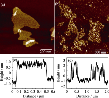
Fig. 1shows the AFM images of GO before and after Nafion modification. The thickness of these two-dimensional materials and their surface morphology were clearly illustrated in the figure. It can be seen the surface of GO is smooth and flat before Nafion modification. The particle size of GO was about 400 nm (Fig. 1(a)), and the thickness was about 1nm (Fig. 1(c)). When GO was modified with Nafion, a large number of small particles were found evenly distributed on the nano sheets even after the long-time sonication (Fig. 1(b)). Although some particles appeared on the mica substrate, it can be seen that these particles tend to be adsorbed onto the surface of GO. The height of these small molecular particles is 2-3 nm (Fig. 1(d)). Agglomeration is not observed between the layers of the GO sheets, which suggests that a small amount of Nafion can effectively modify the surface of GO without damaging its dispersion.
Fig. 1 AFM height image of GO (a), GO modified with Nafion (b) and the height profiles of GO (c) and GO modified with Nafion (d)
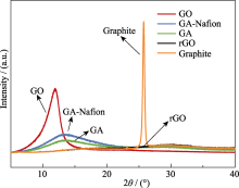
Fig. 2 is XRD patterns of graphene, flake graphite, rGO, and GA and GA-Nafion powders. (002) characteristic peaks of GO and flake graphite are 11.85° and 25.74° respectively, corresponding to the inter-layer space 0.75 nm and 0.35 nm. The inter-layer space increase from graphite to GO was attributed to the oxygen- containing functional groups on carbon layers. These functional groups facilitated the peeling of carbon layer from densely packed graphite. The characteristic peak disappeared at rGO, which indicates the restoration graphene plane. The aerogel prepared by GO with or without Nafion modification had similar peaks at 13.37° and 13.17° respectively, representing the inter-planar space of 0.66 nm and 0.67 nm. The characteristic peaks of these two materials show that the oxygen-containing functional groups were not completely removed by EDA reduction.
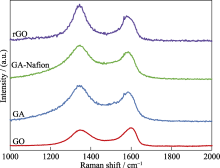
Similar results were also found in Raman spectroscopy. The structure of graphene related materials can be characterized with Raman spectroscopy. Significant peaks denoted as D and G peaks appeared on all the spectra (Fig. 3). The D peak is related to the oscillation of the sp2 carbon bond, but this peak is only activated when there are defects nearby. Therefore, D peak can be used to evaluate the defect density of graphene related materials.And the G peak comes from the first-order scattering of the E2g mode of sp2 domain from the stretching vibration of in-plane C-C bonds[17]. The intensity ratio ID/IG is generally used to quantify the defect density of graphene related materials. ID/IG of GO, GA, GA-Nafion and rGO was 1.13, 1.22, 1.24 and 1.46 respectively. It can be observed that the ratio increased when GO was reduced. Therefore, the removal of oxygen-containing functional groups would leave defects on graphene plane. The ratios of graphene aerogel prepared by GO with or without Nafion modification are very close, indicating that the modification of Nafion does not affect the reaction between graphene and EDA. The high D/G intensity ratio of rGO may be a result of its higher reduction level.
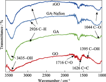
It can be seen more clearly in the FT-IR spectra that there were not significant differences in the composition of these aerogels fabricated through different routes (Fig. 4). The FT-IR spectra of GO shows characteristic peaks of the stretching vibration of hydroxyl group at 3435 cm-1, C==C stretching vibrations of benzene rings at 1626 cm-1, C==O stretching vibrations of carboxylic groups at 1716 cm-1, C-OH stretching vibrations at 1395 cm-1 and C-O stretching vibrations of epoxide group at 1044 cm-1. The peaks of hydroxyl and epoxide groups in rGO, GA and GA-Nafion were weakened because of the reduction by EDA. At the same time, the GA-Nafion shows almost the same spectrum as GO. Characteristic peaks related to the F atom are not observed after a long time washing, indicating that Nafion adsorbed on the GO nano sheets was completely removed.
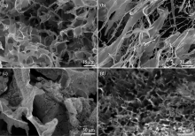
It has been demonstrated that, GA and GA-Nafion has similar composition, but the morphologies were quite different. Fig. 5(a) shows the morphology of GA, which has typical porous structures with pore size of 20-50 µm. It is this porous structure that prevented the agglomeration of graphene, and promoted the performance of graphene aerogel in energy and environment area. Fig. 5(b) is morphologies of GO with Nafion adsorbed on the surface. NumerousNafion nano fibers existed between multi-layer stacked GO sheetthough only small amount of Nafion was added. It was clearly demonstrated in Fig. 5(c) and (d) that, the structure of graphene aerogel was significantly changed when GO nano sheets were pre-modified with Nafion. GA-Nafion had a multi-scale porous structure, with macropores about 100 µm, and micropores about 1µm. As graphene aerogel was freeze-dried during the preparation, such macropores were likely formed during the crystallization of ice, and the micropores were formed because of the absorbed Nafion molecules.
Fig. 5 SEM morphologies of GA (a), GO nano sheets modified with Nafion (b), GA-Nafion (c) and its high resolution morphology (d)
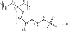
Fig. 6 is the structure of Nafion molecule which has long hydrophobic fluorocarbon chains and hydrophilic sulfonic groups[18]. When Nafion was added into GO dispersion, the sulfonic groups formed hydrogen bonds with carboxyl and epoxy groups of GO. And the off-plane fluorocarbon chains could prohibit the stacking GO nano sheets. Also, Nafion would form micelles with hydrophobic cores and hydrophilic surfaces when it is distributed in water because of its bipolar structure. These micelles became soft templates to form micropores with GO attached on the surfaces. The soft template effect and prohibited agglomeration lead to the formation of micropores. The multi scale porous structure was a combination of macropores from ice and micropores from Nafion.
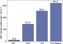
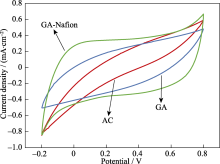
The different performance of two kinds of graphene aerogels was demonstrated in the BET specific surface area and electrochemical properties. As shown in Fig. 7, the specific surface area of the powder obtained by the direct drying of GO was only 32.8 m2/g, and the specific surface area of rGO after freeze-drying was increased to 437.4 m2/g. GA has even higher specific surface area, which came from the network formed between EDA and GO sheets (763.9 m2/g). The specific surface area of GA- Nafion was increased to 967.8 m2/g, which was more close to the theoretical area of graphene material[2]. The result demonstrated that the multi-scale porous structure of aerogel improved the specific surface area. This material may have great application prospects in the application areas that require relatively high specific surface area. Fig. 8 shows the electrochemical cyclic voltammetry curves of activated carbon, GA and GA-Nafion. The specific capacities of AC, GA and GA-Nafion calculated from the figure were 51.7, 103.4, and 146.1 F/g, repectively. GA has better electrochemical performance than activated carbon, which may be attributed to its high surface area. The performance of multi- scale porous GA-Nafion was enhanced more significantly. This indicates that graphene aerogel prepared through Nafion modified GO has better performance for its specicial porous sturcture.
This study demonstrates that Nafion can act as a surfactant to modify the surface of GO nano sheets. And the graphene aerogel prepared through Sol-Gel methods with this modified GO sheets exhibits multi-scale porous structures, with macropores 50-100 µm in size, and micropores about 1 µm. This special graphene aerogel has large specific surface areas close to 967.8 m2/g, showing better electrochemical performance over traditional graphene aerogel.
The authors have declared that no competing interests exist.
| [1] |
Honeycomb carbon: a review of graphene . |
| [2] |
Science . |
| [3] |
Electrochimica Acta . |
| [4] |
Nano Energy . |
| [5] |
Nano Letters . |
| [6] |
RSC Advances . |
| [7] |
Advanced Materials . |
| [8] |
The fabrication, properties, and uses of graphene/polymer composites . |
| [9] |
Nano Letters . |
| [10] |
Wrinkles and folds of activated graphene nanosheets as fast and efficient adsorptive sites for hydrophobic organic contaminants . |
| [11] |
ACS Applied Materials & Interfaces . |
| [12] |
Small . |
| [13] |
Frontiers in Materials . |
| [14] |
Chemical Society Reviews . |
| [15] |
Journal of Materials Chemistry . |
| [16] |
Scientific Reports . |
| [17] |
Applied Physics A: Materials Science & Processing . |
| [18] |
Imaging heterogeneity and transport of degraded Nafion membranes . |

/
| 〈 |
|
〉 |