王舒玮
WANG Shu-Wei
中图分类号: TQ174
文献标识码: A
文章编号: 1000-324X(2017)06-0596-07
通讯作者:
收稿日期: 2016-08-17
修回日期: 2016-11-13
网络出版日期: 2017-06-20
版权声明: 2017 无机材料学报编委会 This is an open-access article distributed under the terms of the Creative Commons Attribution License, which permits unrestricted use, distribution, and reproduction in any medium, provided the original author and source are credited.
基金资助:
作者简介:
作者简介: 王舒玮(1992-), 女, 硕士研究生.
展开
摘要
固体电解质界面膜(Solid Electrolyte Interphase, SEI)在钠离子电池(Sodium Ion Battery, NIB)中扮演着重要作用。迄今为止, 对于钠离子电池SEI膜的探索仍然十分有限。本研究利用电化学原子力显微镜(Electrochemical AFM, EC-AFM), 通过循环伏安法研究了钠离子电池负极材料高定向热解石墨(Highly Oriented Pyrolytic Graphite, HOPG), 在碳酸乙烯酯(Ethylene Carbonate, EC)和氟代碳酸乙烯酯(Fluoroethylene Carbonate, FEC)电解液中首次充放电过程SEI膜的结构变化。通过纳米刻蚀的方法, 进一步获得首次充放电结束后SEI的厚度。结合X射线光电子能谱(X-ray Photoelectron Spectroscopy, XPS)分析了HOPG在EC和FEC电解液中所形成的SEI膜的化学组成区别。研究结果表明, 在EC电解液中, 所生成的SEI膜在HOPG表面非台阶处较薄, 但在HOPG的台阶处较厚; 在FEC电解液中, 所生成的SEI膜很厚, 具有明显的双层结构。其中上层是由体积较大的颗粒组成, 下层则由致密的小颗粒组成。
关键词:
Abstract
Chemical and morphological structures of solid electrolyte interphase (SEI) play a vital role in sodium-ion battery (NIB). Up to date, SEI remains the least understood component in NIB due to its trace presence, delicate chemical nature, heterogeneity in morphology, elusive formation mechanism, and lack of reliable in situ quantitative characterization tools. SEI morphological evolution during the first cyclic voltammetry and the thickness of SEI after first discharging-charging cycle on highly oriented pyrolytic graphite (HOPG) surface were investigated by using in situ electrochemical atomic force microscopy (EC-AFM). Complemented by an ex situ XPS analysis, the differences in interfacial features and fundamental constitution of SEI formation in ethylene carbonate (EC) and fluoroethylene carbonate (FEC)-based electrolytes on HOPG electrode surface were revealed. In 1 mol/L NaClO4/EC/DMC electrolyte, dense films were formed at the step edges, while thinner films were observed on the basal plane. In 1 mol/L NaClO4/EC/DMC electrolyte, stable films with doubled layer structures were formed on HOPG electrode after initial electrochemical cycling. The upper layer was composed of large particles, which was soft and easy to be scrapped off by AFM tip while the under layer was composed of dense small particles.
Keywords:
当今世界, 能源的存储与转换越来越成为制约人类经济可持续发展的重要问题。储能技术是平衡各类能量应用需求, 提升社会整体能量使用效率的重要手段。在各类储能技术中, 电化学储能技术具有重要的地位。在各种电化学储能技术中, 锂离子电池以其工作电压高、容量高、自放电小和循环寿命长等优点而在便携式电子市场得到广泛应用。然而在长期使用、存储, 特别是在极端条件下, 锂离子电池的稳定性和安全性问题仍是制约其更大规模应用的重要因素。
可充电电池的电化学性能很大程度上取决于电解液与电极在固液相界面上发生反应, 形成的覆盖于电极材料的固体电解质界面膜(简称SEI膜)的物理和化学特性。SEI膜是离子的导体, 电子的绝缘体。SEI膜的形成会在首次充放电过程中导致不可逆的容量损失, 但是性能优异的SEI膜可以有效阻止电解液进一步在电极上得失电子而发生氧化还原副反应, 消耗锂源, 降低充放电效率。因此SEI膜在具有化学反应活性的电极和电解液之间起着重要的保护作用[1]。
扫描探针显微镜(Scanning Probe Microscopy, SPM)主要包括扫描隧道显微镜(Scanning Tunneling Microscopy, STM)和原子力显微镜(Atomic Force Microscopy, AFM), 是检测电子电流和表面形貌的有效工具[2-11]。由于SEI膜是电子的绝缘体, 所以STM在SEI膜研究方面的应用非常有限[12]。AFM是基于探针与样品之间作用力的一种检测技术, 可以直观的观察到界面反应和形貌变化。通过原位AFM可以直观地监测SEI膜随着电化学电位变化的动态演变过程。另外, 可以原位研究电解液变化, 对SEI膜的形成带来的影响[13-21]。
在锂离子电池中, SEI膜对石墨负极的循环稳定性和倍率性能有显著的影响[22-26]。进一步研究表明, 由于电解液的分解和电解液在电极界面上的反应, SEI膜有着极为复杂的化学组成, 如ROCO2Li、ROLi、LiF、Li2CO3等, 并且有着复杂的结构[1, 21]。我们前期结合AFM和XPS, 探究了锂离子电池SEI膜的形成过程及其化学组成, 发现氟代碳酸乙烯酯(FEC)可以有效改善SEI膜的力学性能并抑制副反应, 从而提高电极材料和整个电池的电化学性能[21]。
由于钠的储量比锂更为丰富, 钠离子电池有望替代锂离子电池应用于大规模能源存储[27-28]。因为钠与钠离子插层化合物更高的化学反应活性, SEI膜在钠离子电池中扮演着更为重要的角色[23, 29-34]。但由于缺乏有效的原位表征手段, 目前对于钠离子存储材料SEI膜的探索十分有限[20, 35]。本工作通过电化学原子力显微镜(EC-AFM)观察HOPG电极在充放电过程中表面形貌的演变过程, 结合XPS分析, 研究了以EC和FEC为基本成分的电解液在HOPG电极上所形成SEI膜的形貌结构及化学组成区别[36]。
将电化学原子力显微镜(EC-AFM)设备(Bruker Icon AFM以及辰华电化学工作站)放置在充满高纯氩气气氛的手套箱中(MBRAUN, H2O≤0.1×10⁻⁶, O2≤0.1×10⁻⁶), 试验在室温条件下进行。电化学系统以高定向热解石墨(HOPG, ZYB等级, 12 mm× 12 mm× 2 mm)作为工作电极, 以金属钠作为对电极和参比电极(CE和RE)。试验开始前, 用透明胶带撕掉HOPG表面, 以获得一个平整干净的工作电极表面。电解液为1 mol/L NaClO4溶解在碳酸乙烯酯/碳酸二甲酯和氟代碳酸乙烯酯/碳酸二甲酯混合溶液中(EC/DMC和FEC/DMC, 体积比是1︰1)(杉杉公司)。为了在HOPG上生成SEI膜, Na-HOPG电解池在扫描电压范围3.0~0 V之间, 以0.5 mV/s的扫描速率进行循环伏安(CV)测试。用氮化硅涂层探针(探针型号: SCANNASYST-FLUID+, k = 0.7 N/m)在峰值力模式下进行形貌图像采集和厚度分析。采用同样的探针, 利用纳米刻蚀的方法, 通过接触模式加大针尖与样品的作用力刮掉HOPG表面SEI膜。
使用岛津公司的仪器测试X射线光电子能谱(Kratos Axis Ultra)。激发源为单色器Al Kα射线(hv=1486.6 eV), 分析范围是300 μm × 700 μm。样品从Na-HOPG电解池中移出, 先用DMC轻微清洗以除去表面残余的盐和溶剂, 再静置晾干后转移至XPS实验装置中。上述过程均在氩气气氛下完成。样品结合能采用污染碳C1s ( 284. 8 eV) 对其它谱峰进行荷电校正。在同一位置, 先对样品的SEI膜表面进行测试分析, 再用Ar离子对其进行刻蚀, 并对刻蚀后的位置进行测试分析。
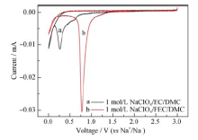
电化学循环伏安法和AFM表征都是在氩气气氛保护的手套箱中进行的。HOPG是一种具有光滑表面和优良导电性的高纯度碳材料, 是观察SEI膜形成过程的理想基底。循环伏安法的扫描速率是0.5 mV/s, 电压范围是3.0~0 V, 扫描方向是3.0V→0 V→3.0 V。图 1显示了HOPG在1 mol/L NaClO4/ EC/DMC电解液和1 mol/L NaClO4/ FEC/DMC电解液中的首次循环伏安曲线。在1 mol/L NaClO4/EC/DMC电解液中, 循环伏安曲线在0.8 V附近开始出现还原峰, 意味着SEI膜开始形成, 在0.25 V时出现一个尖锐的还原峰, 但在之后的充电过程中并未出现氧化峰, 这说明钠电池电解液分解所形成的SEI膜是不可逆的。在1 mol/L NaClO4/FEC/DMC电解液中, 其尖锐的还原峰出现在电压0.75 V附近, 意味着FEC电解液更容易被还原, 生成SEI膜的电位更高。
图1 在1 mol/L NaClO4/EC/DMC电解液中和1 mol/L NaClO4/FEC/DMC电解液中的第一圈循环伏安曲线(电压范围: 3.0~0 V, 速率: 0.5 mV/s)
Fig. 1 Cyclic voltammogram of HOPG electrode in 1 mol/L NaClO4/EC/DMC and 1 mol/L NaClO4/FEC/DMC at scan rate of 0.5 mV/s
2.2.1 EC/DMC电解液中SEI膜的形成
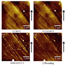
图 2是在1 mol/L NaClO4/EC/DMC电解液中, 第一次循环伏安循环时, HOPG电极表面形貌演变过程。图 2(a)显示加入电解液后, CV电压在3.0~ 2.84 V范围内, HOPG电极上有纳米级的小颗粒, 这可能由于污染物分解产生的。图 2(b)显示在电压降低到大约为0.13 V时, HOPG的台阶处开始有钝化膜产生。随着电压进一步减小, 大量小颗粒覆盖满HOPG的表面, 其中以在HOPG的台阶处钝化尤为明显。图2(c, d)显示, 随着之后阳极电流的上升中, 表面形貌保持不变直至电化学循环伏安结束。
图2 在1 mol/L NaClO4/EC/DMC电解液中首次电化学循环伏安的原位AFM图片
Fig. 2 In situ AFM images of HOPG electrode cycled at a scanning rate of 0.5 mV/s between 3.0 and 0 V in 1 mol/L NaClO4/EC/DMC(a) During discharging, potential range of 3.0-2.84 V; (b) During discharging, potential range of 0.24-0.04 V; (c) The potential is sweeped from 0.04 V to 0 V then rised to 0.13 V; (d) During charging, potential range of 2.98-3.0 V. The arrow indicates AFM scanning direction
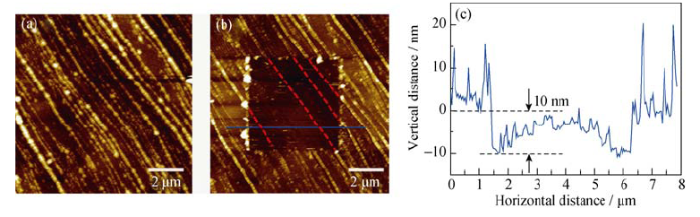
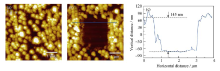
在上述电化学循环伏安结束后, 移动探针扫描位置, 选取另一个区域进行表征, 如图 3。从图 3(a)发现SEI膜正如原位AFM过程中观察到的一样, 在HOPG的台阶处钝化尤为明显, 集聚着更多的纳米颗粒, SEI膜更厚。为了获得SEI膜的厚度信息, 在第一次循环伏安循环结束后, 将AFM切换到接触模式, 通过加大针尖作用在SEI膜上的力, 刮掉表面SEI膜, 然后采用峰值力模式采集图像, 图3(b)中间5 μm×5 μm的方形区域是刮掉SEI膜的区域。部分被刮掉SEI的膜堆积在方形周围区域, 因此方形周围区域有些地方亮度较大。图 3(b)中红色虚线所示, 将HOPG表面的SEI膜刮掉后, 露出HOPG的台阶部分, 发现与图中未被刮掉SEI膜区域的高度更高的SEI膜线条分布吻合, 表明HOPG的台阶处界面反应的活性更高。图 3(c)为蓝色实线所示位置的高度截面图, 结果显示SEI膜的厚度范围大约为10~30 nm。
图3 (a)HOPG负极在1 mol/L NaClO4/EC/DMC电解液中首次循环伏安结束后的图像; (b)中间SEI膜被刮除后HOPG负极的图像; (c)蓝色实线所示的高度剖面图
Fig. 3 (a) AFM image of HOPG electrode after first CV cycle in the 1 mol/L NaClO4/EC/DMC; (b) AFM image of the HOPG anode after the SEI in the middle of the image being scraped off and (c) cross-section analysis of the location marked by blue line
2.2.2 FEC/DMC电解液中SEI膜的形成
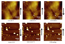
图 4是在1 mol/L NaClO4/FEC/DMC电解液中, 第一次循环伏安循环时, HOPG电极表面的形貌演变过程。图 4(a)显示在加入电解液后, CV电压在3.0~2.85 V范围内, HOPG电极的表面形貌。图 4(b)显示HOPG表面上有少量纳米级的小颗粒, 这可能是由于污染物组分分解产生的。从图 4 (c)可以看出, 致密的SEI膜大约在放电电压为0.85 V时开始生成。随着电压进一步减小, 致密的小颗粒覆盖了HOPG的表面, 并在致密的小颗粒上生成少量大颗粒, 如图 4(d)。图 4(e, f)显示在阳极电流上升过程中, 表面形貌保持不变, 直至电化学循环伏安结束。
图 4 在1 mol/L NaClO4/FEC/DMC电解液中进行首次循环伏安测试的原位AFM图片
Fig. 4 In situ AFM images of HOPG electrode cycled at a scanning rate of 0.5 mV/s between 3.0 and 0.0 V in 1 mol/L NaClO4/FEC/DMC(a) During discharging, potential range of 3.0-2.85 V; (b) During discharging, potential range of 1.06-0.93 V; (c) During discharging, potential range: of 0.93-0.80 V; (d) During discharging, the potential range of 0.66-0.52 V; (e) The potential is sweeped from 0.01 V to 0 V then rised to 0.17 V; (f) During charging, the potential range of 2.90-3.0 V; The arrow indicates AFM scanning direction
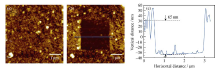
在上述电化学循环伏安结束后, 移动探针扫描位置, 选取另一个区域进行表征, 如图 5。从图 5(a)发现SEI膜具有明显的双层结构, 上层由体积大的颗粒组成, 下层由致密的小颗粒组成。在原位扫图的过程中, 由于上层结构柔软, 且上层SEI膜生成的过程不是连续的膜, 容易在扫图过程被针尖刮掉(即便在微小的作用力下), 所以在原位扫图过程中只观察到了少量的上层大颗粒。由致密小颗粒构成的下层SEI膜结构稳定, 在原位扫图过程中不易被针尖刮掉。在FEC/DMC中得到的SEI膜的厚度信息与在EC/DMC中得到SEI膜的厚度信息类似, 如图5(b)所示, 图像中间2.5 μm×2.5 μm的方形区域是在图 5 (a)的基础上用接触模式刮掉SEI膜的区域。图 5(c)为蓝色实线所示位置的高度截面图, 结果显示SEI膜的厚度大约为145~160 nm。与1 mol/L NaClO4/EC/DMC中形成的SEI膜相比, 在1 mol/L NaClO4/FEC/DMC中形成的SEI膜更厚。用峰值力模式在SEI膜上反复扫图两次即可将上层体积大的颗粒刮掉, 只露出下层致密的小颗粒构成的SEI膜, 如图 6(a)所示。与EC/DMC中得到SEI膜的厚度信息类似, 如图 6(b)所示, 图像中间2.5 μm×2.5 μm的方形区域是刮掉SEI膜的区域, 部分被刮掉的SEI膜部分堆积在方形周围区域, 因此方形周围区域有些地方亮度较大。图 6(c)为蓝色实线所示位置的高度截面图, 结果显示由致密的小颗粒组成的SEI膜下层厚度大约是65~85 nm, 与由大颗粒组成的上层SEI膜的厚度几乎相同。从以上研究结果可以发现在1 mol/L NaClO4/FEC/DMC中形成的SEI膜的组成并不是简单的上下两层的结构, 观察到的下层的SEI膜或许有着更为复杂的多层堆积结构[9]。
图5 (a) HOPG负极在1 mol/L NaClO4/FEC/DMC电解液中首次循环伏安结束后的图像; (b) 中间SEI膜被刮除后HOPG负极的图像; (c) 蓝色实线所示的高度剖面图
Fig. 5 (a) AFM image of HOPG electrode after first CV cycle in the 1 mol/L NaClO4/FEC/DMC; (b) AFM image of the HOPG anode after the SEI in the middle of the image being scraped off; and (c) cross-section analysis of the location marked by blue line
图6 (a) HOPG负极在1 mol/L NaClO4/FEC/DMC电解液中首次循环伏安结束后下层SEI膜的图像; (b) 中间SEI膜被刮除后HOPG负极的图像; (c) 蓝色实线所示的高度剖面图
Fig. 6 (a) AFM image of under SEI layer on HOPG electrode after first CV cycle in the 1 mol/L NaClO4/FEC/DMC; (b) AFM image of the HOPG anode after the SEI in the middle of the image being scraped off; (c) cross-section analysis of the location marked by blue line
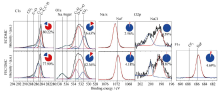
由于AFM难以提供SEI膜化学组成方面的信息, 所以我们使用XPS作为辅助, 更加深入地探究SEI膜的化学组成结构。图7所示的是HOPG在EC/DMC和FEC/DMC电解液中生成的SEI膜的主要元素的图谱。在C1s谱图中, 284.8 eV处有C-C、C-H峰, 这是碳氢化合物的污染峰和SEI膜有机物组分中的碳原子与碳原子或氢原子成键峰; 在285.5和287.2 eV处, 出现C-O和C=O峰; 在289.1 eV处, 出现碳酸盐组分峰, 这是碳酸钠或碳酸烷基酯类化合物。在O1s谱图中, 与氧原子有关联的碳酸烷基酯类化合物在532.4 eV处出现较强的峰。通过Na1s谱图发现, FEC电解液中生成SEI膜中NaF的组分较多。通过Cl2p谱图发现, SEI膜中无机物NaCl组分含量很少。结合F1s谱图, FEC电解液中生成的SEI膜主要无机物组分的是NaF。在SEI膜表面分析化学组分的同一位置, 用Ar离子对SEI膜进行部分刻蚀后, 再分析化学组成。随着高度的变化, SEI膜中各种化学组分含量有相应的改变(表 1)。结果显示, SEI膜内层的无机物组分的含量略有一些提高。XPS的化学组成研究结果, 表明HOPG电极表面SEI膜的主要化学组成是含C和O的有机物组分。
图7 在EC/DMC和FEC/DMC电解液中进行电化学循环伏安(电压范围: 3.0~0 V; 速率: 0.5 mV/s)后, HOPG负极上SEI膜的XPS图谱
Fig. 7 XPS spectra of the SEI on HOPG electrode cycled at a scanning rate of 0.5 mV/s between 3.0 and 0 V in the EC/DMC and FEC/DMC electrolytes
表1 XPS测试结果C、O、Na、Cl和F的原子百分比
Table 1 Atomic concentrations of C, O, Na, Cl and F obtained from XPS
| HOPG | Atomic concentration /% | |||||
|---|---|---|---|---|---|---|
| C | O | Na | Cl | F | ||
| 1 mol/L NaClO4 /EC/DMC | Before etching | 80.22 | 16.63 | 2.56 | 0.59 | - |
| After etching | 83.16 | 11.62 | 3.42 | 1.80 | - | |
| 1 mol/L NaClO4 /FEC/DMC | Before etching | 77.90 | 12.36 | 4.18 | 0.87 | 4.69 |
| After etching | 78.02 | 5.21 | 6.95 | 2.03 | 7.79 | |
利用电化学原子力显微技术原位研究了钠离子电池HOPG电极在首次电化学循环过程中的形貌变化。研究结果表明, 在1 mol/L NaClO4 EC/DMC和1 mol/L NaClO4 FEC/DMC电解液中, 所形成的SEI膜的形貌和结构有明显的差异。在EC电解液中, SEI膜在HOPG平面处的致密层很薄, 在HOPG台阶处钝化膜较厚。在FEC电解液中, SEI膜很厚, 可以观察到明显的双层结构。其中, 上层由体积较大的颗粒组成, 结构柔软, 容易被AFM探针刮掉; 下层SEI膜由致密的小颗粒组成。结合XPS分析发现, 在两种电解液中, SEI膜的主要组成都是含C、O的有机聚合物组分, 无机物组分含量很少。SEI膜的化学组成和形貌结构均随着深度的变化而变化。
致密且厚的SEI膜, 在循环过程中可以更好的保护电极材料, 但是过厚的SEI膜不可避免的会增加离子的传输阻力。因此, 有必要合理控制SEI膜的厚度、组成, 从而进一步优化电池性能。以上研究结果显示利用原位电化学原子力显微技术结合XPS成分分析来评估SEI膜的性质是一个非常有效的途径, 有利于设计高性能钠离子电池电解液组分和添加剂。
The authors have declared that no competing interests exist.
| [1] |
Electrolytes and interphases in Li-ion batteries and beyond. |
| [2] |
Nanoscale patterning of a self-assembled monolayer by modification of the molecule-substrate bond. |
| [3] |
Structure of isophthalic acid based monolayers and its relation to the initial stages of growth of metal-organic coordination layers.
|
| [4] |
Isophthalic acid: a basis for highly ordered monolayers.
|
| [5] |
Oligo (naphthylene- ethynylene) Molecular Rods.
|
| [6] |
Self-assembled monolayers of a bis(pyrazol-1-yl)pyridine-substituted thiol on Au(111).
|
| [7] |
Steering supramolecular patterns by nucleobase-terminated molecules.
|
| [8] |
In situ study of topography, phase and volume changes of titanium dioxide anode in all-solid-state thin film lithium-ion battery by biased scanning probe microscopy.
|
| [9] |
Direct observation of inhomogeneous solid electrolyte interphase on MnO anode with atomic force microscopy and spectroscopy. |
| [10] |
Facet dependent SEI formation on the LiNi(0.5)Mn(1.5)O4 cathode identified by in situ single particle atomic force microscopy.
|
| [11] |
3D visualization of inhomogeneous multi-layered structure and Young's modulus of the solid electrolyte interphase (SEI) on silicon anodes for lithium ion batteries. |
| [12] |
STM study on graphite/electrolyte interface in lithium-ion batteries: solid electrolyte interface formation in trifluoropropylene carbonate solution. |
| [13] |
In situ and quantitative characterization of solid electrolyte interphases. |
| [14] |
In situ observation of electrolyte-concentration-dependent solid electrolyte interphase on graphite in dimethyl sulfoxide.
|
| [15] |
In situ AFM studies of SEI formation at a Sn electrode.
|
| [16] |
In Situ AFM study of surface film formation on the edge plane of HOPG for lithium-ion batteries.
|
| [17] |
Morphology and modulus evolution of graphite anode in lithium ion battery: an in situ AFM investigation.
|
| [18] |
AFM study of oxygen reduction products on HOPG in the LiPF6-DMSO electrolyte.
|
| [19] |
In-situ investigation of solid-electrolyte interphase formation on the anode of Li-ion batteries with atomic force microscopy.
|
| [20] |
Atomic force microscopy studies on molybdenum disulfide flakes as sodium-ion anodes. |
| [21] |
In situ AFM imaging of solid electrolyte interfaces on HOPG with ethylene carbonate and fluoroethylene carbonate-based electrolytes. |
| [22] |
Superior electrochemical performance and storage mechanism of Na3V2(PO4)3 Cathode for Room-Temperature Sodium-Ion Batteries. |
| [23] |
Sodium storage and transport properties in layered Na2Ti3O7 for room-temperature sodium-ion batteries. |
| [24] |
Interfacing electrolytes with electrodes in Li ion batteries.
|
| [25] |
Nanostructured anode material for high-power battery system in electric vehicles.
|
| [26] |
Nanostructured carbon-based electrodes: bridging the gap between thin-film lithium-ion batteries and electrochemical capacitors. |
| [27] |
Update on Na-based battery materials. A growing research path. |
| [28] |
Sodium-ion batteries. |
| [29] |
Better cycling performances of bulk Sb in Na-ion batteries compared to Li-ion systems: an unexpected electrochemical mechanism. |
| [30] |
Study of the reactivity of Na/hard carbon with different solvents and electrolytes.
|
| [31] |
Reversible insertion of sodium in tin.
|
| [32] |
Controlling SEI formation on SnSb-porous carbon nanofibers for improved Na ion storage.
|
| [33] |
Prototype sodium-ion batteries using an air-stable and Co/Ni-Free O3-layered metal oxide cathode.
|
| [34] |
Advanced sodium-ion batteries using superior low cost pyrolyzed anthracite anode: towards practical applications. |
| [35] |
Electrochemical Na insertion and solid electrolyte interphase for hard-carbon electrodes and application to Na-ion batteries. |
| [36] |
In situ and operando atomic force microscopy of high-capacity nano-silicon based electrodes for lithium-ion batteries. |

/
| 〈 |
|
〉 |