


等离子喷涂热障涂层残余应力的实验与模拟研究
[杨加胜1, 2, 3 , 于建华4 , 钟兴华1, 2 , 赵华玉1, 2 , 周霞明1, 2 , 陶顺衍1, 2  , 丁传贤
, 丁传贤1, 2 ]
, 丁传贤|
|


分别采用真空和大气等离子体喷涂工艺在GH3128镍基高温合金基材表面制备CoNiCrAlY结合层和氧化钇部分稳定的氧化锆陶瓷层组成热障涂层。采用有限元模拟计算了涂层的残余应力, 研究了基材预热对打底层与陶瓷层界面应力分布的影响规律。结果表明, 预热基材可以显著地降低陶瓷顶层内部产生的残余拉应力。采用钻孔法测量了涂层中的残余应力并与模拟结果作定量比较, 结果表明: 有限元模拟计算结果与实验测量结果能较好吻合。
, DING Chuan-XianFinite element analysis (FEA) was performed to analyze residual stresses development within thermal barrier coatings system consisting vacuum plasma sprayed CoNiCrAlY bondcoat and atmospheric plasma sprayed yttria partially stabilized zirconia topcoat on the GH3128 nickel-based superalloy substrates. The effect of substrate preheating process on the residual stress generated at the bondcoat/topcoat interface was evaluated. The results show that substrate preheating process reduces tensile stresses within the coating. To provide quantitatively comparison to the computational results, hole-drilling method was used to evaluate the residual stresses. The measured residual stresses are in agreement with the numerical simulation results obtained from FEA.
Plasma-sprayed thermal barrier coatings (TBCs) have been used to protect the high-temperature components of gas turbines, which consists of a multilayered coating with nickel-based superalloy substrate, oxidation-resistant metallic bondcoat, usually MCrAlY (M is Ni or/and Co) and ceramic topcoat which is typically 7wt%-8wt% yttria-stabilized zirconia (YSZ). Residual stress is usually induced among the sprayed splats ( i.e., quenching stress) and caused by the thermal expansion coefficient (TEC) mismatch between the substrate and coating ( i.e., thermal stress). Residual stresses have attracted much attention since it affects various types of coating performance, such as thermal shock resistance and thermal cycling life[ 1, 2, 3, 4, 5]. Therefore, investigation on the stresses after deposition and thermal exposures can provide a deep understanding of coating failure mechanisms.
In present work, commercially available finite element analysis (FEA) program was employed to simulate the temperature distribution and internal stresses development during the deposition of YSZ coating, including both the quenching stress and thermal stress contributions. Hole drilling method was utilized to measure the residual stresses in the whole coatings, which would provide quantitatively comparison with stress distribution obtained from FEA.
To evaluate the residual stress distribution within coatings, finite element model was established using ANSYS APPL code. As shown in Fig. 1, the model consists of superalloy substrate, vacuum plasma sprayed CoNiCrAlY bondcoat and atmospheric plasma sprayed YSZ topcoat. With regard to the numerical calculations, the simulated parameters were selected to correspond with the experiments described in the following section. A symmetric simulated was employed to reduce data processing time. The major assumptions involved in the simulation were given subsequently. (1) The substrate/bondcoat and bondcoat/topcoat interfaces were assumed to be flat, neglecting the effect of grit blasting prior to deposition process. (2) The effect of porosity and thermal contact resistance were neglected in the model. Perfect bonding between layers of the coating was assumed. (3) Additionally, it must be noted that the oxidation of the bondcoat was not considered in the model.
 | Fig. 1 Partial-section view of finite element mesh for TBC systemMaterial properties data used in the FEA were summarized in Table 1. To calculate the stress generated in the spraying process, the topcoat was considered as a hot block at the melting temperature of 2680℃ and tied to the underlying materials (substrate+bondcoat) at a given uniform preheating temperature. The latter was successively considered to be 25℃, 227℃ or 427℃ to study the effect of initial preheating temperature of the substrate. The topcoat elements were assumed to be in a solid phase at melting temperature, implying that contraction of the elements when they were in liquid phase did not generate significant stresses. |
During the deposition process, as the plasma gun traverse back and forth across the coating, convection heat absorption from the plasma jet dominated the heat loss from the front face. Heat was lost from the back surface of the substrate by convection. After the deposition process, heats were lost from both surface of the topcoat and substrate to the ambient air by convection. Note that heat transfer by radiation was estimated to be two orders of magnitude lower than convection and four orders of magnitude lower than conduction[ 6]. Therefore, radiation heat was not included in the simulation. The heat transfer coefficients for the surface of the substrate/ambient air and topcoat/plasma gas were 8 and 320 W/(m2•K), which were chosen from literature[ 7, 8]. The bulk gas temperature at the top surface was chosen as 427℃ for depositing ceramic topcoat[ 9].
The Co32Ni21Cr8Al0.5Y(Amdry995, Sulzer Metco) bondcoat was fabricated by vacuum plasma spraying on grit blasted GH3128 nickel-based substrate, followed by atmospheric plasma-sprayed topcoat of YSZ. Rectangular substrate with a dimension of 30 mm×20 mm×2 mm. The thicknesses of the CoNiCrAlY bondcoat and YSZ topcoat were about 100 µm and 300 µm, respectively. Commercially available 8wt% yttria- stabilized zirconia (Metco 204NS, Sulzer Metco) powder was used as feedstock to deposit the coating. The medium size ( D50) of YSZ powder is 56.1 µm. The PT-A2000 vacuum and atmospheric plasma spraying system equipped with F4-VB and F4-MB plasma guns (Sulzer Metco AG, Wohlen, Switzerland) were applied to deposit CoNiCrAlY and YSZ coatings, respectively. Detailed plasma spraying parameters were given in Refs[ 10, 11].
Morphologies of YSZ coatings were examined using a field emission electron microscope (SEM, JSM 6700F, JEOL, Tokyo, Japan) and an EPMA-8705 QH2 electron probe microstructure analyzer (Shimadzu, Tokyo, Japan). Thermal diffusivity of YSZ coating was measured, using a laser method, as a function of temperature in the range from 200℃ to 1200℃ on φ10.3 mm×0.8 mm samples. The coefficient of thermal expansion was obtained by measuring temperature-dependent change of specimen length using a high-temperature dilatometer (Model 402, Netzsch) from room temperature to 1200℃ in air. The specimen was prepared to be a cuboid with a size of 26 mm×5 mm×2.5 mm. All measured values of YSZ properties are listed in Table 1.
The detailed procedure of measuring stress by using hole drilling technique was given in Ref.[ 12] and will be briefly described here. The residual stresses in the coating specimen around the drilled hole were relaxed due to the hole drilling and can be determined by detecting the deformation on specimen surface. For measuring the deformation, the strain gage rosette was applied and the directions of the rosette were distributed along 0°, 45° and 90°. Three strain components ( ε0, ε45 and ε90) in each direction before and after drilling hole can be obtained and the in-plane stresses for the equivalent drilling depth can be determined by Hooke’s law[ 12]. The through-thickness stress field was determined by means of the incremental hole-drilling and the tests were conducted by carrying out successive drilling steps of 50 µm in depth with a 1 mm diameter hole. After drilling, the specimens were cross- sectioned in order to determine the coating thickness and the depth of the hole by means of SEM observations.
Figure 2 shows SEM images of as-sprayed coatings. It was proposed to illustrate some important characteristics of the microstructure. The main characteristic of the coatings exhibits lamellar structure of superposed and oriented layers, which are the results of the forming process. The pores and voids appear as dark spots in the micrographs of the cross-section, as shown in Fig. 2(a). Vertical microcracks are also observed in Fig. 2(b). These cracks resulted from the quenching stresses generated during the plasma spraying process.
 | Fig. 2 Cross-section SEM images of YSZ topcoat revealing pores and microcracks (a) and vertical cracks between splat layers (b) |
Figure 3 shows the radial quenching stress through the CoNiCrAlY and YSZ layers of the TBCs generated after the hot topcoat layer depositing onto the underlying materials (substrate+bondcoat) by FEA. It should be noted that the radial stress profiles are plotted to be continuous at dissimilar interface by taking the average of nodal solutions at the interface. It is found that the quenching stresses within the topcoat are in tensile state (~ 180 MPa). The radial residual stress generated after the coating system cooled to room temperature will be described in the subsequent section 3.4.
 | Fig. 3 Radial quenching stress through the CoNiCrAlY and YSZ layers of the TBCs. |
Figure 4 and Fig. 5 show the distributions of axial and shear stress along radius at the bondcoat/topcoat interface calculated through FEA after TBC system cooled to room temperature. Modeling results show that there are remarkable stresses concentration at the edge of the interface. Near the longitudinal axial ( x=0 mm), the axial and shear stresses are zero at the bondcoat/topcoat interface. Near the free edge, both axial and shear stresses state gradually change from compressive to tensile along the interface radius. The maximum value of tensile axial stress is found to be ~64 MPa within the topcoat near the free edge, as shown in Fig. 4.
 | Fig. 4 Axial stress at the bondcoat/topcoat interface as a function of radial direction |
 | Fig. 5 Shear stress at the bondcoat/topcoat interface as a function of radial direction |
The tensile axial stress may cause spallation of the coating. Interfacial cracks initiated at the free edge can propagate radially toward the central region, causing a progressive delamination. Close to the free edge, the maximum tensile shear stress of 46 MPa occurrs at the bondcoat/topcoat interface (Fig. 5). This large stress can be attributed to either shear or mixed modes of failure of coatings[ 8].
The effect of the initial preheating temperature of the substrate on the radial stress distribution after spraying process was summarized in Fig. 6. From the figure, it can be seen that the preheating temperature of 227℃ significantly reduced the stress generated within the topcoat. A low tensile stress with a magnitude of approximately 44 MPa was found at the bondcoat/topcoat interface. Preheating temperature of 427℃ had a greater effect on the stress distribution that stress state changed from tensile to compressive within the topcoat and a compressive stress in the order of 22 MPa was located at the bondcoat/topcoat interface. The preheating process increased substrate temperature, and hence reduced the quenching stress within coating. Moreover, the preheating process also resulted in a higher compressive thermal stress, which was generated when the coating cooling to ambient temperature. Since the residual stress was the summation of quenching and thermal stress, the residual stress was lower when the contribution of the compressive thermal stress was higher. It was well known that tensile stress could induce microcracks initiated near the bondcoat/topcoat interface, whereas compressive stress could effectively restrain the propagation of the cracks. Therefore, the substrate should be preheated prior to the deposition process in order to achieve reliable TBC components in most applications.
 | Fig. 6 Effect of substrate preheating on the radial stress at the interface as a function of radial direction |
In order to verify the numerically calculated residual stress, a comparison between the calculated stresses and the experimental residual stress measurements were depicted in Fig. 7. The measured stresses distribution in the coating agreed well with the FEA results could be detected. Tensile residual stresses could be found in the topcoat and bondcoat, while compressive zone was located in the substrate. An average radial tensile stress up to 18 MPa was determined in the YSZ topcoat layer by the hole-drilling measurement, while the simulation result was 24 MPa. The tensile radial stress may cause cracks within ceramic coatings. These cracks were perpendicular to the substrate surface as shown in Fig. 2(b). The residual stress values in the bondcoat were tensile state. In the middle position of the layer (350 µm), measured and modeled stress were 97 MPa and 160 MPa, respectively. In the substrate, deviations between calculation and measurement values maybe related to the grit blasted process. Because the grit blasted step would induce compressive stresses into the substrate, whereas no grit blasted process was included for the simulation. The deviation value of measured and modeled compressive stress in the substrate (600 µm) was approximately 220 MPa, which was in good agreement with previous experimental data that approximately 250 MPa compressive stress would generated in the substrate during grit blasted process[ 13].
 | Fig. 7 Comparison between measured and simulated residual stress profiles in the coating |
The residual stress plays an important role in deter mining the failure mode of the coatings. Usually, it can be recognized that the residual tensile stress can make the crack initiation, grow and propagate. The residual compressive stress can make the crack to be closed. But the residual compressive stress can also make the coating to failure in the coating system[ 14, 15]. Figure 8 shows the failure modes of coating under different stress state, it can be seen that the tensile stress can cause coating delaminating (Fig. 8(a)) or bridged crack (Fig. 8(c)) and eventually induce the fracture of coating normal to interface. However, the residual compressive stress can make the coating edge delamination (Fig. 8(b)) and bulking (Fig. 8(d)) and will further cause delamination driven by bulking (Fig. 8(e)) and eventual spallation of coating, as shown in Fig. 8(f). It can be seen that the compressive stress can prompt the crack initiation and propagation along the interface, whether spallation will occur or not is determined by the relative fracture strengths of the interface and coating.
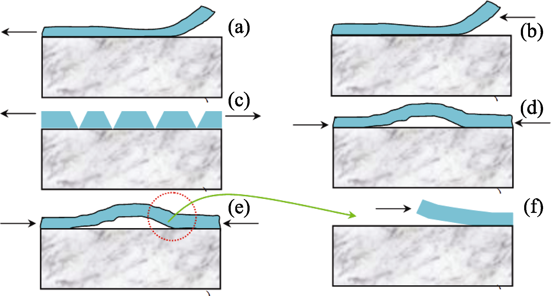 | Fig. 8 Failure modes of a coating under residual stress(a) Delamination under tensile stress; (b) Edge delamination under comprethessive stress; (c) Bridged crack; (d) Bulking; (e) Bulking driven delamination; (f) Eventual spallation of coating |
Finite element model was used to estimate residual stress generated during plasma spray process. FEA revealed that the interfaces between dissimilar materials were the critical location since residual stresses concentration located in these areas. Moreover, the simulated results showed the beneficial effect of substrate preheating process on reducing residual stress distribution in TBC system. Compared to 25℃, preheating temperature of 227℃ of the substrate resulted in a lower tensile stress generated in the YSZ topcoat, while preheating temperature of 427℃ leaded residual stress state turn from tensile to compressive. Furthermore, comparison between the calculated by FEA and hole-drilling experimental through-thickness residual stress values, a good agreement can be obtained.
Acknowledgments:The authors would like to thank Mr. W. Wu for the SEM observations. We also express our appreciation to Mr. Cai A. and Ms. Gao J.H. for the thermal diffusivity and elastic modulus measurements and Prof. Chen J.B. (Department of Engineering Mechanics, Shanghai Jiaotong University) for the residual stresses measurement. Appreciation is also given to Dr. Yang K. for his helpful comments. We also express our great gratitude for the simulation platform and software support from university of Chinese Academy of Sciences.
| [1] |
|
| [2] |
|
| [3] |
|
| [4] |
|
| [5] |
|
| [6] |
|
| [7] |
|
| [8] |
|
| [9] |
|
| [10] |
|
| [11] |
|
| [12] |
|
| [13] |
|
| [14] |
|
| [15] |
|